Method and system for controlling turbomachine with control saturations management

A turbine engine and control system technology, applied in the direction of turbine/propulsion fuel delivery system, engine components, engine control, etc., can solve the problems of complex implementation, unsatisfactory use of turbine engines and unsatisfactory correctors

Pending Publication Date: 2021-11-12
SAFRAN AIRCRAFT ENGINES SAS
View PDF9 Cites 0 Cited by
  • Summary
  • Abstract
  • Description
  • Claims
  • Application Information

AI Technical Summary

Problems solved by technology

The second solution is complex to implement and its complexity increases with the number of inputs / outputs
The method implemented by the system relies on the reverse transmission of the corrector, which cannot be used for all turbine engines
[0017] Therefore, prior art solutions to overcome desynchronization of commands saturated by limiters are not satisfactory

Method used


Image

  • Method and system for controlling turbomachine with control saturations management
  • Method and system for controlling turbomachine with control saturations management
  • Method and system for controlling turbomachine with control saturations management

Examples


Embodiment Construction

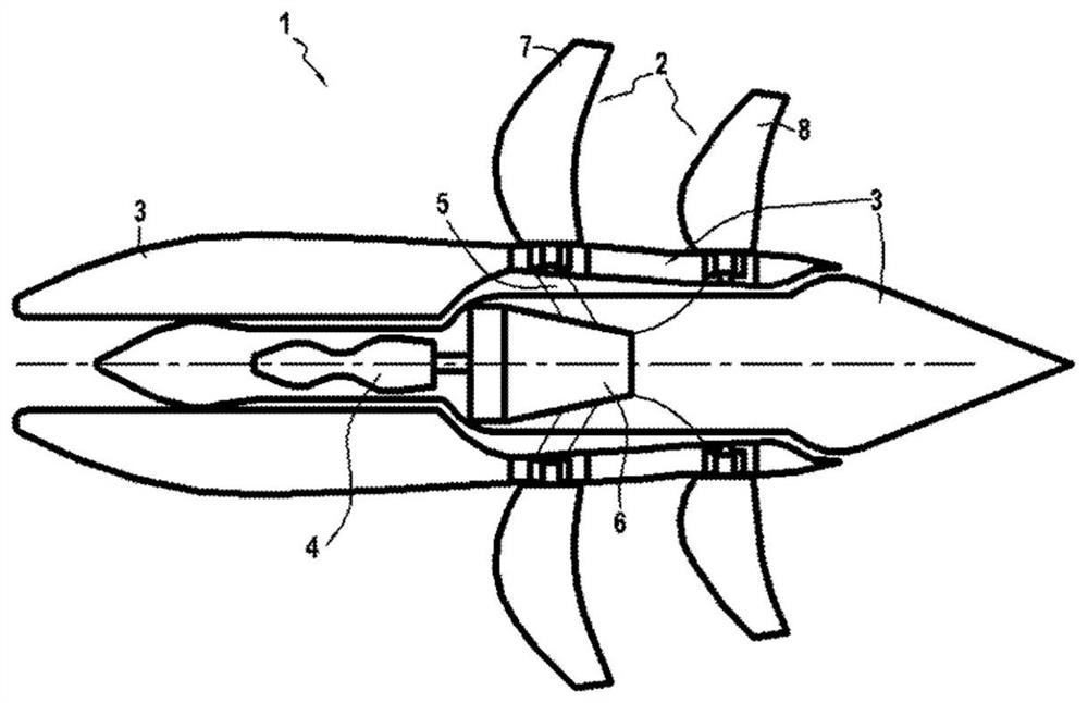
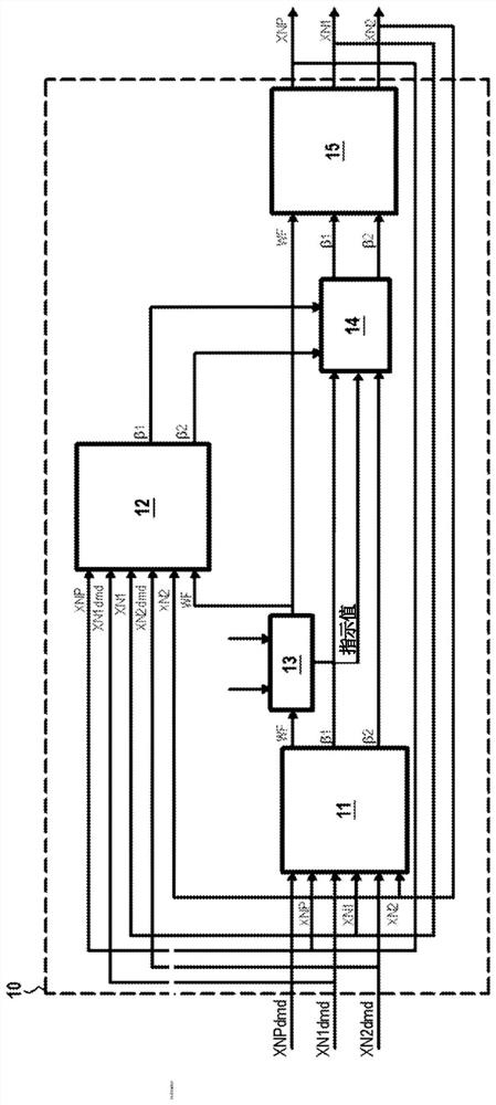
[0049] image 3 A system 10 for controlling a turbine engine according to an embodiment of the invention is schematically represented. The turbine engine controlled by the control system 10 according to the invention may be a turbine engine 1 with an unducted fan, e.g. figure 2 Turbine engine described in.

[0050] The control system 10 includes a first corrector 11 , a second corrector 12 , a first selection unit 13 , a second selection unit 14 and an integrator 15 .

[0051] The first corrector 11 comprises three outputs delivering a first value for each of the three controlled quantities. The first control amount corresponds to the fuel flow WF of the open rotor 1, and the second control amount corresponds to the pitch β of the upstream propeller of the open rotor 1 1 , the third control amount corresponds to the pitch β of the downstream propeller of the open rotor 1 2 .

[0052] The first corrector 11 receives as input the values ​​of three variables of the open rot...


PUM


Abstract

A method for controlling the first, second and third variables of a turbine engine according to the first, second and third control variables of the turbine engine, each of which may be saturated according to an operating parameter of the turbine engine. The method comprises delivering a first multivariable correction (120) of a first value for the three control variables; selecting (130) a first control variable to be delivered as a function of the minimum value, the maximum value and a value determined by the first correction; delivering a second multivariate correction (140) of a second value for the second and third control variables; and selecting (150) the values of the second and third control variables to be delivered among the values determined during the first correction and the values determined during the second correction.

Description

technical field [0001] The present invention relates to the field of control systems for turbine engines, in particular turboprop engines or turbine engines with unducted fans (also known as unducted single fans or USFs). Background technique [0002] figure 1 denotes a turbo engine with an unducted fan or an unducted fan according to the prior art. Such as figure 1 As shown, an unducted fan 1, also known as an open rotor, is an aircraft turbojet engine whose fan 2 is fixed directly outside the power turbine and nacelle 3, allowing increased engine power compared to a ducted turbojet engine Bypass ratio, thereby reducing fuel consumption. [0003] The open rotor is usually equipped with a gas generator 4 and a free turbine 5 driving two counter-rotating variable pitch propellers 7 and 8 through a reduction gearbox 6 . [0004] Such as figure 2 As shown, it schematically represents the system for controlling the open rotor 1. From the command point of view, the open rot...

Claims


Application Information

Patent Timeline
Patent Type & Authority Applications(China)
IPC IPC(8): F02K3/04F02C3/04F02C9/00
CPCF02K3/04F02C3/04F02C9/00F02C9/48F01D7/00F02C9/58F05D2260/74F05D2270/304B64D31/06B64D2027/005Y02T50/60F05D2220/323F05D2270/336
Inventor 蒂费纳·拉斯兰克里斯托夫·马克·亚历山大·勒·布伦西尔文·克莱蒙特
Owner SAFRAN AIRCRAFT ENGINES SAS
Why Eureka
Try Eureka