Mounting structure of front auxiliary frame of new energy vehicle

A front subframe and mounting structure technology, applied in the substructure, vehicle components, transportation and packaging, etc., can solve the problems of many fixtures, high manufacturing costs, complex structures, etc., and achieve the effect of increasing absorption and improving anti-collision ability

Pending Publication Date: 2021-11-16
CHERY COMML VEHICLE ANHUI
View PDF7 Cites 1 Cited by
  • Summary
  • Abstract
  • Description
  • Claims
  • Application Information

AI Technical Summary

Problems solved by technology

[0004] The front sub-frame structure of existing models is generally composed of stamping parts and tailor-welded. The structure is complex, and many fixtures are required for welding. It is difficult to control the size of welding with a large area, and the manufacturing cost is relatively high. General models cannot afford it. ;It is connected with the body by bolts, and the rigidity and strength are relatively low
Not conducive to driving and collision energy absorption

Method used


Image

  • Mounting structure of front auxiliary frame of new energy vehicle
  • Mounting structure of front auxiliary frame of new energy vehicle

Examples


Embodiment Construction

[0023] In order to make the objects, technical solutions, and advantages of the present invention, the embodiments of the present invention will be further described in detail below with reference to the accompanying drawings.

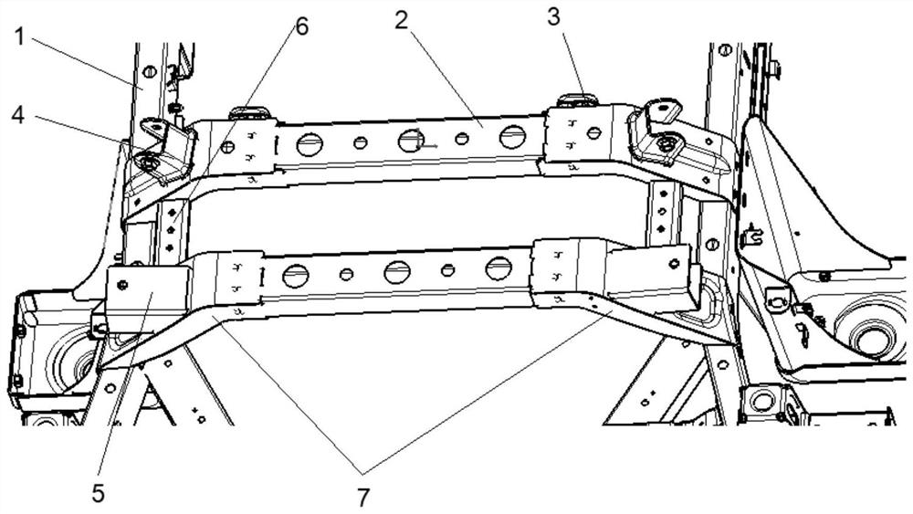
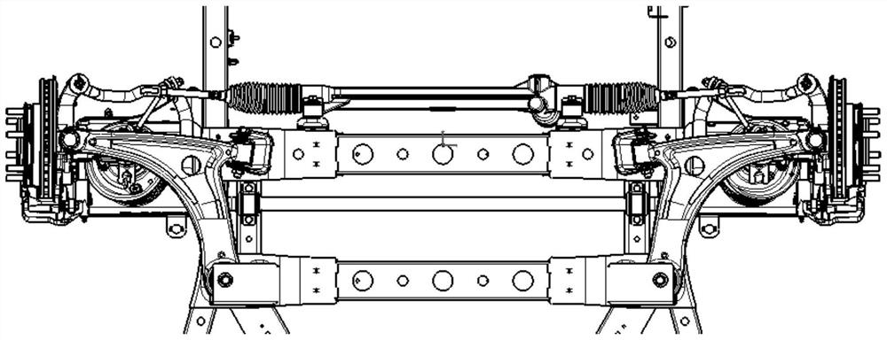
[0024] See Figure 1-2 , Install front subframe structure of a new energy vehicles, it has:

[0025] Frame rail;

[0026] Front subframe cross member, mounted on both ends of the frame rails; front cross member comprises a first sub-frame before the sub-beam and the second sub-frame front cross member;

[0027] Under the arm front bracket, mounted on the front ends of the first sub-frame cross member;

[0028] Diverter fixing bracket mounted on the front ends of the first sub-frame cross member;

[0029] Lower rear arm bracket, mounted on both ends of the second sub-frame front cross member;

[0030] Stabilizer bar fixed bracket, a first end portion connected to the front cross member and the second sub-frame before the sub-beam.

[0031] The front ends of ...


PUM


Abstract

The invention discloses a mounting structure of a front auxiliary frame of a new energy vehicle. The mounting structure comprises frame longitudinal beams; a front auxiliary frame cross beam, wherein the two ends of the front auxiliary frame cross beam are mounted on the frame longitudinal beams; the front auxiliary frame cross beam comprises a first front auxiliary frame cross beam and a second front auxiliary frame cross beam; lower swing arm front supports which are installed at the two ends of the first front auxiliary frame cross beam; steering gear fixing supports which are installed at the two ends of the first front auxiliary frame cross beam; lower swing arm rear supports which are mounted at the two ends of the second front auxiliary frame cross beam; and transverse stabilizer bar fixing supports which are connected with the end parts of the first front auxiliary frame cross beam and the second front auxiliary frame cross beam, so that the collision resistance of the frame can be improved, and collision energy can be effectively absorbed and relieved during collision.

Description

Technical field [0001] The present invention belongs to the technical field of new energy vehicles, in particular, it relates to a mounting structure of the front sub-frame, a new energy vehicles. Background technique [0002] With the improvement of people's living standards, the automotive industry has been a very big development, automobile-related research and design more and more deeply. Automotive front subframe is one of the important structural automotive components, connected between a vehicle body and suspension, and the supporting body and engine assembly. In the design of the front subframe, a number of factors need to be considered. [0003] During the implementation of the present invention, the inventors found that the prior art has at least the following problems: [0004] The front subframe structure of the generally used conventional models tailored blank stamped product configuration, complex structure, more desired welding jig, and the large area is difficult ...

Claims


Application Information

Patent Timeline
Patent Type & Authority Applications(China)
IPC IPC(8): B62D21/11B62D21/02
CPCB62D21/11B62D21/02
Inventor 刘虎陈鹏周阵阵陈尚志周娟娟
Owner CHERY COMML VEHICLE ANHUI
Why Eureka
Try Eureka