Small cargo transfer equipment for warehousing service

A small, cargo technology, applied in the field of small cargo transfer equipment for warehousing services, can solve the problems of easy shaking of goods, no plywood to clamp the goods, falling on the ground, etc., to save space resources, improve work efficiency, and reduce the frequency of shaking Effect

Active Publication Date: 2021-11-16
深圳市杨诚吉运物流有限公司
View PDF13 Cites 0 Cited by
  • Summary
  • Abstract
  • Description
  • Claims
  • Application Information

AI Technical Summary

Problems solved by technology

[0005] In order to overcome the traditional cargo transfer equipment, it does not have the function of limiting the cargo, and there is no splint to clamp the cargo. When the cargo is transferred, the cargo is easy to shake and fall to the ground, resulting in d

Method used


Image

  • Small cargo transfer equipment for warehousing service
  • Small cargo transfer equipment for warehousing service
  • Small cargo transfer equipment for warehousing service

Examples


Embodiment 1

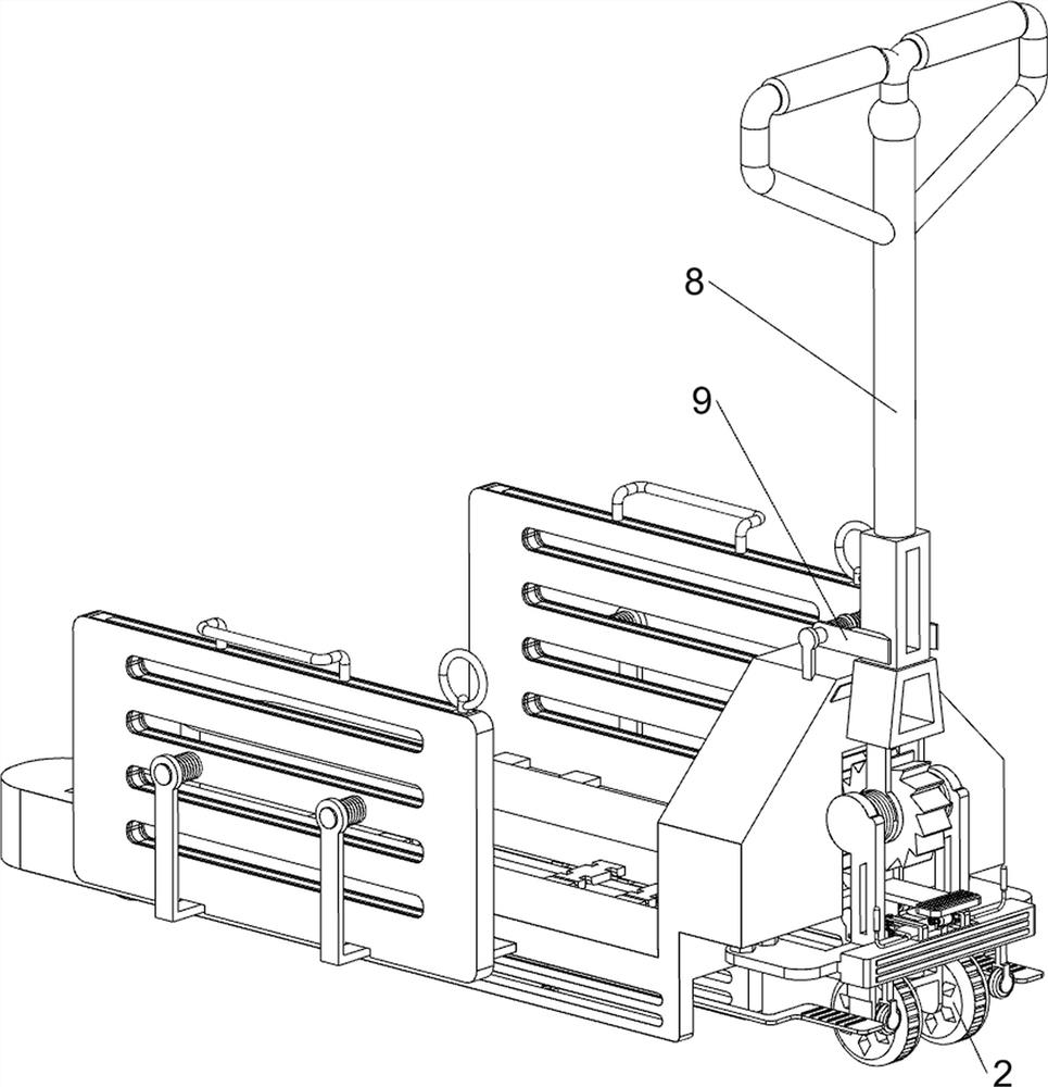
[0036] A small cargo transfer equipment for warehousing services, such as figure 1 , figure 2 , image 3 , Figure 4 , Figure 5 , Figure 12 and Figure 13As shown, it includes a first rotating shaft 1, a wheel 2, a lifting frame 3, a connecting frame 4, a prismatic column 5, a second rotating shaft 6, a third rotating shaft 7, a tow bar 8, a stabilizing component 9 and a lifting component 10, and the connecting frame 4. Two prismatic columns 5 are installed symmetrically front and rear on the left side of the top. A lifting frame 3 is slidingly connected between the prismatic columns 5. The inside of the lifting frame 3 is connected with a first rotating shaft 1 in a symmetrical front and back rotation on the left side, and the bottom of the connecting frame 4 The right front and rear symmetrical rotation type is equipped with a second rotating shaft 6, the first rotating shaft 1 is provided with wheels 2, the second rotating shaft 6 bottom symmetrical rotation type is...

Embodiment 2

[0041] On the basis of Example 1, such as Figure 6 , Figure 7 , Figure 8 , Figure 9 , Figure 10 , Figure 11 , Figure 14 , Figure 15 and Figure 16 As shown, a clamping assembly 11 is also included, and the clamping assembly 11 includes a clamping plate 1101, a groove plate 1102, a first sliding plate 1103, a second sliding plate 1104, a pull rod 1105, a second spring 1106, a buckle 1107 and a third spring 1108, the left and right sides inside the lifting frame 3 are all front and rear symmetrically slidingly connected with clamping plates 1101, the left and right sides in the middle of the lifting frame 3 are also connected to the forward and backward symmetrical clamping plates 1101, and the outsides of the middle two clamping plates 1101 are all sliding Both are connected with a groove plate 1102, and the groove plate 1102 is connected with the clamping plate 1101 on the outside. The first slide plate 1103 is slidably installed on the inside of the groove plat...


PUM


Abstract

The invention relates to transfer equipment, in particular to small cargo transfer equipment for warehousing service. The technical problem to be solved is to provide the small cargo transfer equipment for the warehousing service, which can adjust the width and the height and has a limiting effect. According to the technical scheme, the small cargo transfer equipment for the warehousing service comprises a connecting frame; two prismatic columns which are symmetrically arranged on one side of the top of the connecting frame; a lifting frame which is arranged between the prismatic columns in a sliding manner; first rotating shafts which are symmetrically and rotatably arranged on one side of the interior of the lifting frame; and a second rotating shaft which is rotatably arranged on one side of the bottom of the connecting frame. According to the size and height of goods, groove plates can be moved outwards, a first sliding plate and a second sliding plate can be moved upwards, and therefore the width between the groove plates and the height of the first sliding plate and the second sliding plate are adjusted, and the working efficiency of goods transferring by people is improved.

Description

technical field [0001] The invention relates to a transfer device, in particular to a small cargo transfer device for warehousing service. Background technique [0002] Warehousing service is a form of service that uses self-built or leased warehouses, venues, storage, storage, loading, unloading, handling and distribution of goods, and charges storage fees from the depositor. [0003] With the continuous development of the logistics industry, most of the transfer equipment is used in the logistics industry. Today, the traditional cargo transfer equipment does not have the function of limiting the cargo, and there is no splint to clamp the cargo. When the cargo is transferred, the cargo It is easy to shake and fall to the ground, causing damage to the goods and causing economic losses, and it cannot be adjusted according to the volume and height of the goods, reducing the work efficiency of goods transfer and other problems. [0004] To sum up, it is necessary to design a s...

Claims


Application Information

Patent Timeline
IPC IPC(8): B65G1/04
CPCB65G1/04B65G1/0492
Inventor 宋海霞
Owner 深圳市杨诚吉运物流有限公司
Why Eureka
Try Eureka