
Soil nail anti-pulling fastening structure

A technology for fastening structures and soil nails, which is applied in basic structure engineering, sheet pile walls, excavation, etc., can solve problems such as inconvenience in the processing process, and achieve the effects of convenient processing, strengthening the fastening effect, and reducing the possibility of

Inactive Publication Date: 2021-11-16
瑞腾基础工程技术(北京)股份有限公司
View PDF8 Cites 1 Cited by
  • Summary
  • Abstract
  • Description
  • Claims
  • Application Information

AI Technical Summary

Problems solved by technology

[0004] In view of the related technologies mentioned above, the inventor believes that the existing soil nails generally use steel bars of various specifications. When fastening the soil nails, it is necessary to tap the soil nails, and the soil nails of different specifications need to be matched. The matching fastening sleeve is very inconvenient in the process of processing

Method used


Image

  • Soil nail anti-pulling fastening structure
  • Soil nail anti-pulling fastening structure
  • Soil nail anti-pulling fastening structure

Examples


Embodiment 1

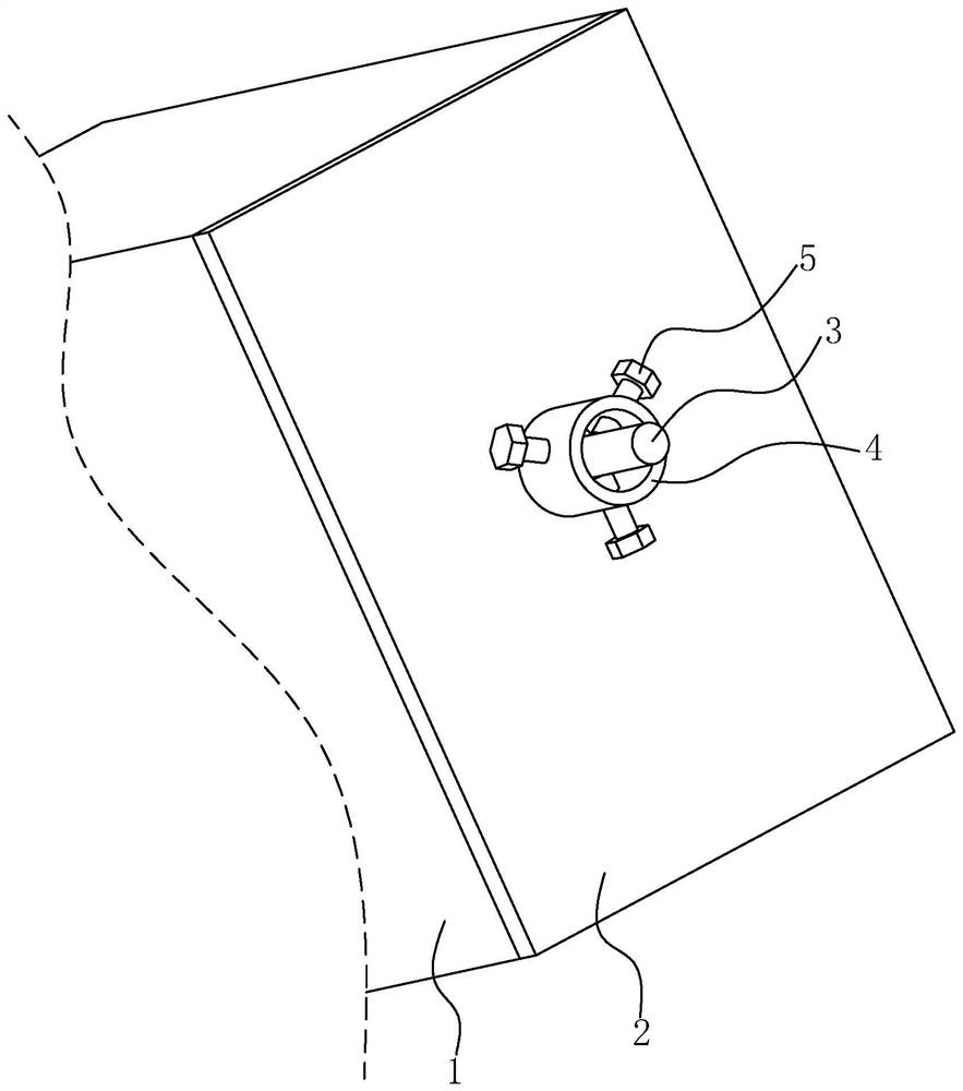
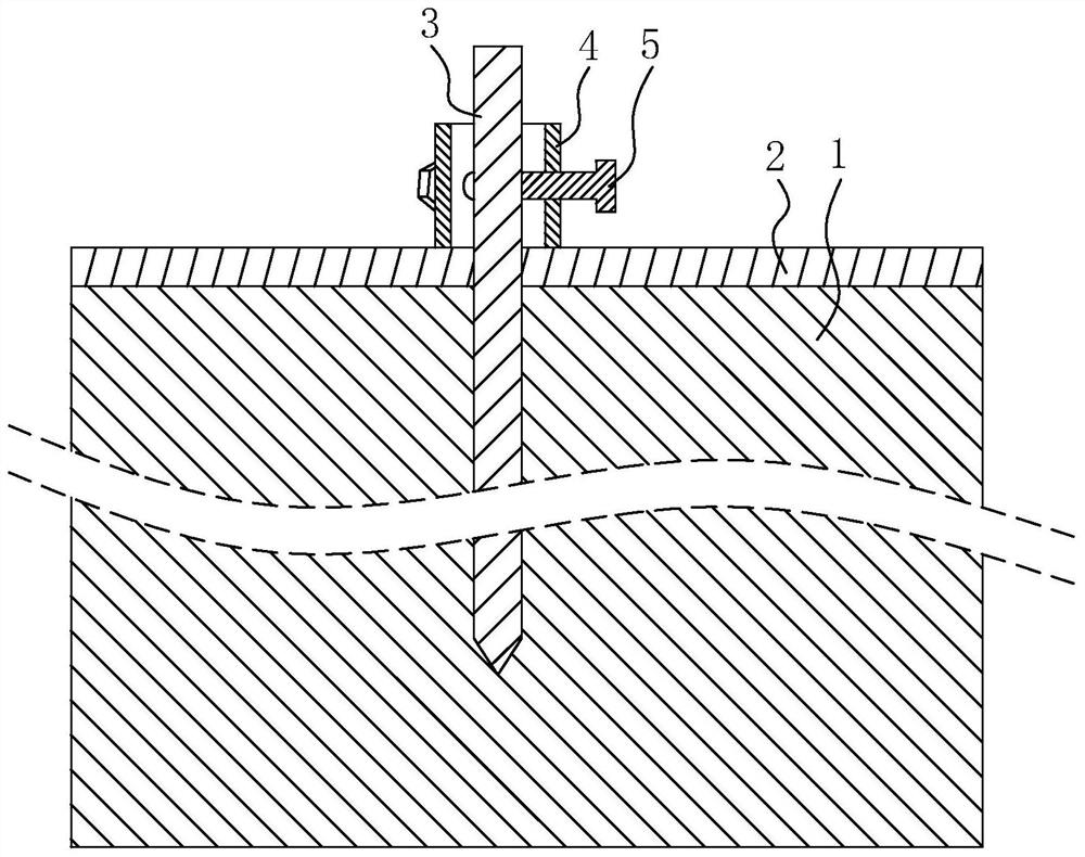
[0036] refer to figure 1 , a soil nail pullout fastening structure, used for fastening the soil nail 3 pierced on the soil 1 and the concrete surface layer 2, including the fastening sleeve 4 set on the soil nail 3 and used for tightening The fastening bolt 5 of the soil-fixing nail 3.

[0037] refer to figure 2 , the end face of the soil nail 3 is higher than the side of the concrete surface layer 2 away from the soil body 1, and the fastening sleeve 4 is cylindrical and pressed against the side of the concrete surface layer 2 away from the soil body 1. The tightening sleeve 4 is arranged coaxially with the soil nail 3, and several tightening bolts 5 are evenly arranged along the circumferential direction of the tightening sleeve 4. In this embodiment, three tightening bolts are arranged in the circumferential direction of the tightening sleeve 4 5. The fastening bolts 5 are set along the radial direction of the fastening sleeve 4, the fastening bolts 5 are penetrated in t...

Embodiment 2

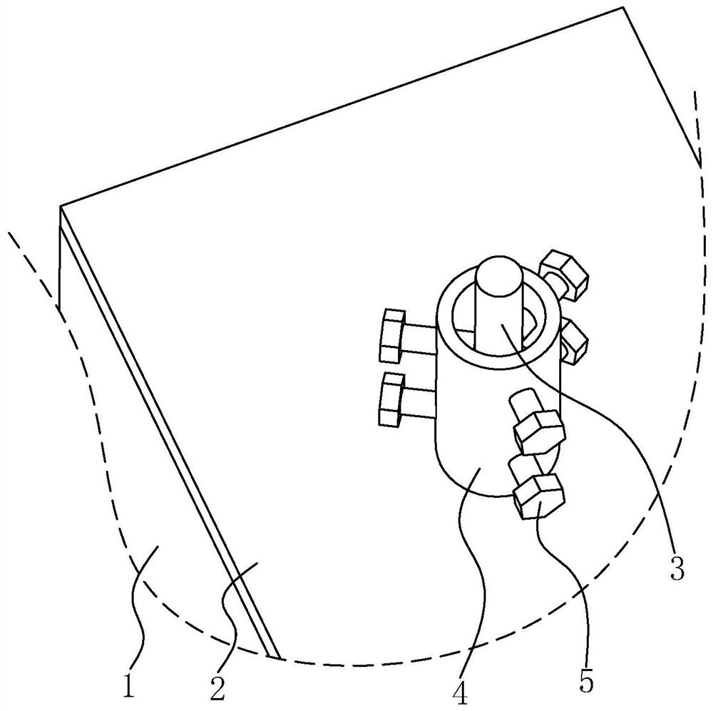
[0040] refer to image 3 The difference between this embodiment and Embodiment 1 is that several fastening bolts 5 are provided along the axial direction of the fastening sleeve 4. In this embodiment, two fastening bolts 5 are provided in the axial direction of the fastening sleeve 4. Fasten the bolt 5.

Embodiment 3

[0042] refer to Figure 4 The difference between this embodiment and Embodiment 1 is that a backing plate 8 is fixedly provided at one end of the fastening sleeve 4 close to the concrete pad, and the soil nail 3 is pierced on the backing plate 8 . The backing plate 8 can increase the contact area between the fastening sleeve 4 and the concrete cushion, and improve the compacting effect on the concrete cushion.


PUM


Abstract

The invention relates to a soil nail anti-pulling fastening structure, and relates to the field of slope support. The soil nail anti-pulling fastening structure is used for fastening a soil nail penetrating through a soil body and a concrete surface layer, and comprises a fastening sleeve arranged on the soil nail in a sleeving mode; the fastening sleeve is pressed on the side, away from the soil body, of the concrete surface layer; a fastening bolt is arranged on the fastening sleeve in a penetrating mode in the radial direction of the fastening sleeve; and the fastening bolt is in threaded connection with the fastening sleeve and tightly abuts against the side face of the soil nail. The soil nail anti-pulling fastening structure has the advantages that tapping on the soil nail is avoided, the fastening sleeve can adapt to soil nails of different specifications, and then the machining process of the soil nail fastening structure is more convenient.

Description

technical field [0001] The present application relates to the field of slope support, in particular to a soil nail pullout-resistant fastening structure. Background technique [0002] Slope support refers to the support, reinforcement and protection measures taken on the slope to ensure the safety of the slope and its environment. [0003] In the existing slope support structure, a layer of concrete surface is often poured on the surface of the slope, and then the concrete surface is penetrated by soil nails and nailed into the soil body, so that the soil nails compress the concrete surface on the soil. In order to prevent the concrete surface from separating from the soil, a fastening sleeve is set on the soil nail for fastening. The soil nail and the fastening sleeve are threaded, and the fastening sleeve is pressed tightly on the concrete surface, so that the soil nail is subject to a certain of prestress. [0004] In view of the above-mentioned related technologies, th...

Claims


Application Information

Patent Timeline
Patent Type & Authority Applications(China)
IPC IPC(8): E02D17/20E02D5/76
CPCE02D17/20E02D5/76
Inventor 王超杨猛猛
Owner 瑞腾基础工程技术(北京)股份有限公司
Learn More