
Objective driving apparatus

A driving device and objective lens technology, applied in the configuration/installation of the head, supporting the head, protecting the transducing head, etc., can solve the problems of low operation efficiency and peeling of the protective part 110, and achieve the effect of reducing the assembly process and stabilizing the protection function

Inactive Publication Date: 2004-01-28
PANASONIC CORP
View PDF1 Cites 0 Cited by
  • Summary
  • Abstract
  • Description
  • Claims
  • Application Information

AI Technical Summary

Problems solved by technology

[0014] Therefore, there is a problem that the protector 110 peels off from the objective lens holder 102 during repeated collisions.
[0015] Moreover, in the fixing operation of the protector 110, in order to prevent the adhesive from adhering to the collision surface, it must be coated, so there is also a problem of low operating efficiency.

Method used


Image

  • Objective driving apparatus
  • Objective driving apparatus
  • Objective driving apparatus

Examples


Embodiment Construction

[0036] Hereinafter, embodiments of the present invention will be described with reference to the drawings.

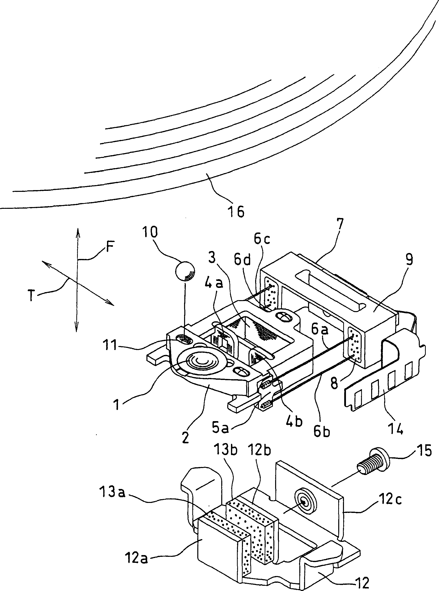
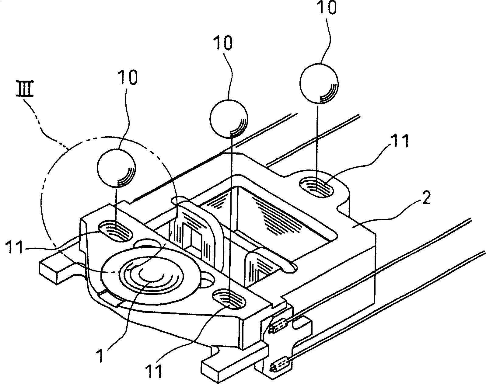
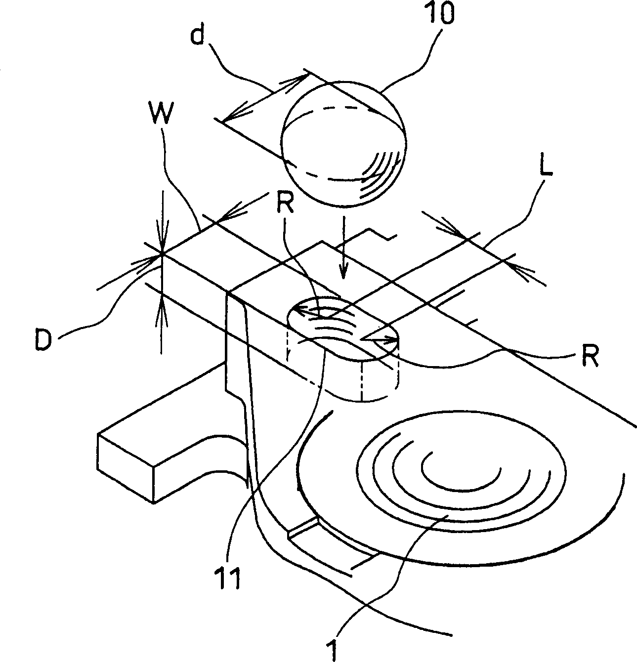
[0037] figure 1 It is an exploded perspective view showing the overall structure of the objective lens driving device in the embodiment of the present invention. figure 1 Among them, 1 is an objective lens, 2 is an objective lens holder, 3 is a focusing coil, 4a, 4b are tracking coils, 5a, 5b are coil substrates (the coil substrate 5b is not shown). On the objective lens holder 2, the objective lens 1, the coil substrates 5a, 5b, the focusing coil 3, and the tracking coils 4a, 4b are respectively fixed at desired positions. Further, the lead terminals of the respective coils are soldered and fixed to the lands of the circuit patterns formed on the coil substrates 5a and 5b. 10 is a protector (protector member), and 11 is a protector mounting part provided on the upper surface of the objective lens holder. The protector 10 is a spherical member made of silicone rubber, ...


PUM


Abstract

An objective lens driving device has a movable portion including an objective lens held by a lens holder, a damage prevention system for preventing the objective lens or a disk from being damaged when the objective lens or the lens holder collides with the disk is provided. The damage prevention system is constituted by inserting a protecting member formed of an elastic member in a fitting portion on an upper surface of the lens holder while being deformed. In this manner, it is possible to generate a sufficient holding power with respect to the protecting member without using glue or the like.

Description

technical field [0001] The present invention relates to an objective lens driving device in a device for optically writing or reading information on a disc-shaped recording medium. Background technique [0002] The objective lens driving device is a kind of deviation of the focal point of the objective lens relative to the information recording surface of the disc-shaped recording medium (hereinafter referred to as the magnetic disk) or the deviation of the optical axis of the objective lens relative to the magnetic track, and the objective lens is directed to the direction perpendicular to the magnetic disk. (hereinafter referred to as the focusing direction) and the radial direction of the magnetic disk (hereinafter referred to as the tracking direction) are driven in two directions to suppress such a deviation. [0003] In recent years, with the increase in the density of disk information and the increase in the speed of disk rotation speed, the above-mentioned control pe...

Claims


Application Information

Patent Timeline
Patent Type & Authority Patents(China)
IPC IPC(8): G11B7/09G11B7/12G11B7/22G11B21/16
CPCG11B7/1201G11B7/0935G11B7/0932G11B7/22G11B21/16G11B7/121
Inventor 毛利政就山本宽
Owner PANASONIC CORP
Learn More