
Method, system, storage medium, and electronic device for adjusting camera angle

An adjustment method and an adjustment system technology, applied in the field of license plate recognition, can solve the problems of low license plate recognition rate, high labor cost, and time-consuming, etc., and achieve the effect of reducing manual adjustment, reducing the number of adjustments, and saving adjustment time

Active Publication Date: 2021-12-21
成都宜泊信息科技有限公司
View PDF13 Cites 0 Cited by
  • Summary
  • Abstract
  • Description
  • Claims
  • Application Information

AI Technical Summary

Problems solved by technology

[0002] With the rapid development of society, the automatic license plate recognition system has been widely used, but the installation angle of the automatic recognition camera of the license plate in the prior art is not the best angle, resulting in a relatively low recognition rate of the license plate. In this case, work is required When personnel go to the scene to manually adjust the license plate recognition camera according to the recognition effect of the license plate recognition camera, it takes a lot of time and labor costs, and the staff can only adjust the angle of the license plate recognition camera based on experience

Method used


Image

  • Method, system, storage medium, and electronic device for adjusting camera angle
  • Method, system, storage medium, and electronic device for adjusting camera angle
  • Method, system, storage medium, and electronic device for adjusting camera angle

Examples


no. 1 example

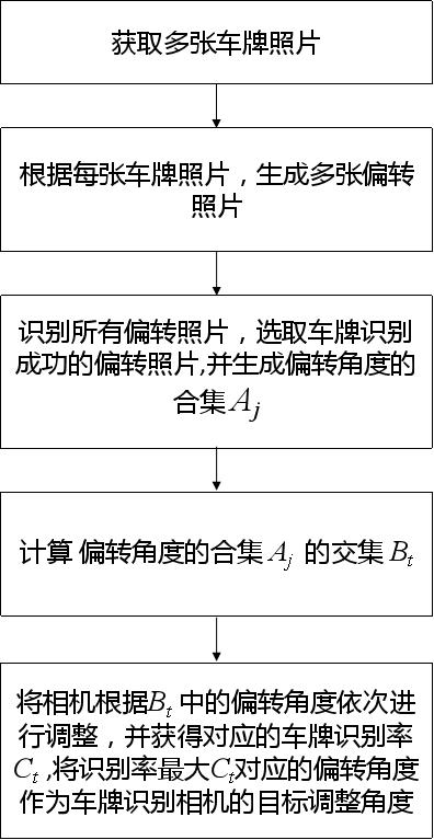
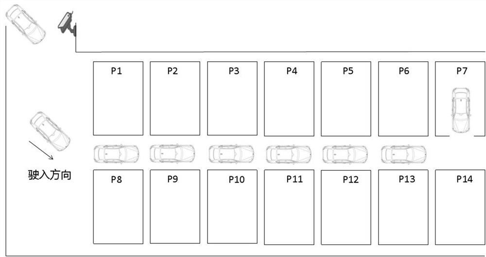
[0036] Such as Figure 1-Figure 3 As shown, the first embodiment of the present invention provides a camera angle adjustment method, including the following steps:

[0037] Step S10: Obtain multiple license plate photos, wherein the serial number of the license plate photos is marked as i, i=1~n, n is the total number of license plate photos;

[0038] Step S20: According to each license plate photo, generate a plurality of deflected photos, where the serial number of the deflected photo is marked as j,j= 1~mi, mi for the first i Total number of deflections for license plate photos, No. j deflection photo relative to the i The deflection angle of a license plate photo is recorded as α j ;

[0039] Step S30: Identify all the deflected photos, select the deflected photos with successful license plate recognition, and set the i The collection of the deflection angles in the deflection photos of successful license plate recognition is denoted as A j ;

[0040] Step S4...

no. 2 example

[0057] The second embodiment of the present invention provides a camera angle adjustment system, including the following modules:

[0058] Obtaining module: used to obtain multiple license plate photos, where the serial number of the license plate photo is marked as i, i=1~n, n is the total number of license plate photos;

[0059] Generating module: used to generate multiple deflected photos according to each license plate photo, wherein the sequence number of the deflected photos is marked as j,j=1~mi,mi for the first i Total number of deflections for license plate photos, No. j deflection photo relative to the i The deflection angle of a license plate photo is recorded as α j ;

[0060] Recognition module: used to identify all deflected photos, select the deflected photos with successful license plate recognition, and convert the first i The collection of the deflection angles in the deflection photos of successful license plate recognition is denoted as A j ;

[...

no. 3 example

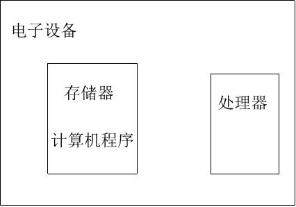
[0066] The third embodiment of the present invention provides a readable storage medium for storing a program, and when the program is executed, it is used to implement the camera angle adjustment method according to any one of the first aspect.


PUM


Abstract

The present invention is applicable to the technical field of license plate recognition, and provides a camera angle adjustment method, system, storage medium, and electronic equipment, wherein a camera angle adjustment method includes the following steps: acquiring multiple license plate photos; Photos, generate multiple deflection photos; identify all deflection photos, select deflection photos with successful license plate recognition, and record the deflection angle collection in each deflection photo with successful license plate recognition as A j ;Calculate; set the camera according to B t deflection angle in α t Adjust in turn, and obtain each time according to the deflection angle α t Adjusted corresponding license plate recognition rate C t , take the corresponding deflection angle as the target adjustment angle of the license plate recognition camera. Through the method for adjusting the camera angle of the present invention, the times of adjusting the camera angle are reduced, the adjustment time is saved, and the recognition rate of successful license plate recognition is improved.

Description

technical field [0001] The present invention relates to the field of license plate recognition, in particular to a camera angle adjustment method, system, storage medium, and electronic equipment. Background technique [0002] With the rapid development of society, the automatic license plate recognition system has been widely used, but the installation angle of the automatic recognition camera of the license plate in the prior art is not the best angle, resulting in a relatively low recognition rate of the license plate. In this case, work is required When personnel go to the scene to manually adjust the license plate recognition camera according to the recognition effect of the license plate recognition camera, it takes a lot of time and labor costs, and the staff can only adjust the angle of the license plate recognition camera based on experience. Contents of the invention [0003] The purpose of the present invention is to provide a camera angle adjustment method, sys...

Claims


Application Information

Patent Timeline
Patent Type & Authority Patents(China)
IPC IPC(8): G06K9/20
Inventor 燕志强彭积祥杨涛
Owner 成都宜泊信息科技有限公司
Learn More