
Method for improving cleaning coverage rate of movable cleaning robot and system thereof

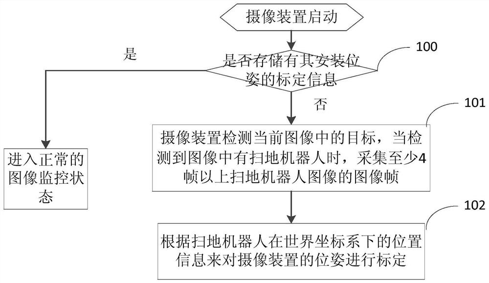
A cleaning robot and coverage technology, applied in cleaning machinery, cleaning equipment, machine parts, etc., can solve problems such as limited MCU computing power, gyroscope output angle drift, map physical space error, etc., to improve cleaning coverage, The effect of solving incomplete cleaning and improving intelligence

Active Publication Date: 2021-11-19
HANGZHOU EZVIZ SOFTWARE CO LTD
View PDF5 Cites 0 Cited by
  • Summary
  • Abstract
  • Description
  • Claims
  • Application Information

AI Technical Summary

Problems solved by technology

[0003] For the mobile cleaning robot using inertial navigation, it uses the odometer carried by the mobile cleaning robot itself and the gyroscope installed on the mobile robot body to construct the map. During the process, the collision between the fuselage and table legs and other objects is involved, resulting in the drift of the output angle of the gyroscope.
In addition, during the movement of the wheels of the mobile cleaning robot, due to the phenomenon of slipping, the output distance of the odometer will drift
[0004] Even for mobile cleaning robots using lidar or visual cameras, limited by the computing power of the MCU, the resolution of the established map cannot be set to a particularly high resolution, and there are still certain errors between the map and the actual physical space.
Due to the existence of mapping and positioning errors, in practice, there are still certain missed scanning areas in the work of mobile cleaning robots

Method used


Image

  • Method for improving cleaning coverage rate of movable cleaning robot and system thereof
  • Method for improving cleaning coverage rate of movable cleaning robot and system thereof
  • Method for improving cleaning coverage rate of movable cleaning robot and system thereof

Examples


Embodiment 1

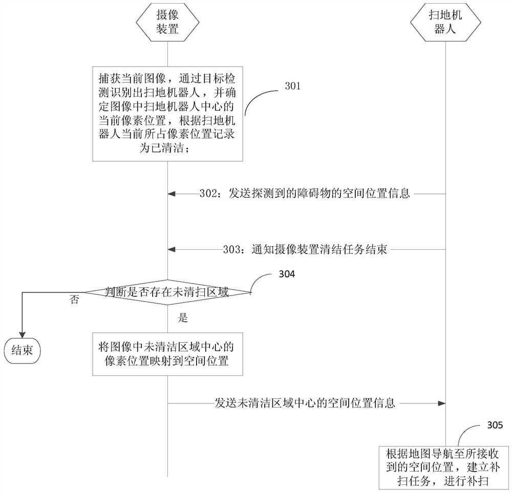
[0081] see image 3 as shown, image 3 It is a schematic flow diagram of the linkage between the camera device and the sweeping robot within its field of view to improve the cleaning coverage.

[0082] Step 301, the camera device records the cleaning path of the sweeping robot according to the captured multi-frame images of the sweeping robot;

[0083] In this step, the camera device captures the current image, recognizes the sweeping robot through target detection, and determines the current pixel position of the center of the sweeping robot in the image (u s , v s ), mark the pixel position occupied by the sweeping robot as cleaning;

[0084] Repeat step 301 to obtain multiple frames of images, determine the spatial position of the sweeping robot in each frame of image, and sequentially connect the pixel positions of the sweeping robot determined based on each frame to obtain the cleaning path trajectory of the sweeping robot in the image.

[0085] In step 302, the clean...

Embodiment 2

[0098] see Figure 5 as shown, Figure 5 It is a schematic flow diagram of the linkage between multiple camera devices and the sweeping robot for supplementary sweeping in this application. In this embodiment, the calibration information of each camera device has been obtained through the calibration process and stored in the body of the camera device respectively. Based on the calibration information, the FOV range of each camera device is converted into the FOV information at the spatial position according to Eq. Notify the sweeping robot; the sweeping robot saves the FOV spatial position information of each camera device, and further, can be mapped to the map.

[0099]Step 501, the sweeping robot locates the current spatial position according to the map, and judges the field of view of the current camera device according to the FOV spatial position information, that is, the sweeping robot determines which camera device or devices it is currently located in, so as to determ...


PUM


Abstract

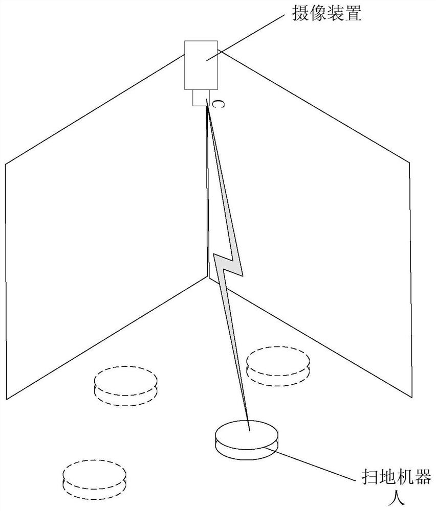
The invention discloses a method for improving cleaning coverage rate of a movable cleaning robot, and the method comprises the steps: enabling a camera device to capture n frames of images at the side of the camera device, determining the pixel position of the movable cleaning robot in each frame of image, and recording the pixel position as a cleaned pixel position; wherein n is a natural number; and determining an uncleaned area in the image according to the position of the cleaned pixel in the image, acquiring spatial position information of the uncleaned area according to the calibration information of the pose of the camera device, and sending the spatial position information to the movable cleaning robot, so that the movable cleaning robot performs supplementary cleaning. According to the invention, external assistance of the mobile robot without human intervention in the cleaning process is realized, the cleaning coverage rate is increased, and the intelligence of the system is improved.

Description

technical field [0001] The invention relates to the field of mobile cleaning robots, in particular to a method for improving the cleaning coverage of a mobile cleaning robot. Background technique [0002] The mobile cleaning robot completes the cleaning based on the constructed map. [0003] For the mobile cleaning robot using inertial navigation, it uses the odometer carried by the mobile cleaning robot itself and the gyroscope installed on the mobile robot body to construct the map. During the process, the collision between the fuselage and table legs and other objects is involved, resulting in the drift of the output angle of the gyroscope. In addition, during the movement of the wheels of the mobile cleaning robot, due to the phenomenon of slipping, the output distance of the odometer will drift. [0004] Even for mobile cleaning robots using lidar or vision cameras, limited by the computing power of the MCU, the resolution of the established map cannot be set to a par...

Claims


Application Information

Patent Timeline
Patent Type & Authority Applications(China)
IPC IPC(8): A47L11/24A47L11/28A47L11/40
CPCA47L11/24A47L11/28A47L11/4002A47L11/4011A47L11/4061A47L2201/04Y02E10/50
Inventor 朱建华苏辉
Owner HANGZHOU EZVIZ SOFTWARE CO LTD
Learn More