A high-precision head frame

A high-precision, headstock technology, which is applied in the direction of grinding frame, grinding drive device, manufacturing tools, etc., can solve the problems of unable to meet the high-precision requirements of shaft parts, unable to keep clean, low transmission accuracy, etc., to maintain Cleanliness, reduce the tolerance of axial movement, and ensure the effect of transmission accuracy

Active Publication Date: 2022-06-17
ZHEJIANG QUANSHUN MACHINE TOOL
View PDF7 Cites 0 Cited by
  • Summary
  • Abstract
  • Description
  • Claims
  • Application Information

AI Technical Summary

Problems solved by technology

[0003] Among them, the head frame in the machine tool is an important part of the machine tool. The head frame of the prior art sets the motor outside the head frame, which will accumulate dust and cannot be kept clean, resulting in low transmission accuracy and cannot meet the high requirements of some shaft parts. Accuracy requirements

Method used


Image

  • A high-precision head frame
  • A high-precision head frame
  • A high-precision head frame

Examples


Embodiment Construction

[0031] The following are specific embodiments of the present invention and the accompanying drawings to further describe the technical solutions of the present invention, but the present invention is not limited to these embodiments.

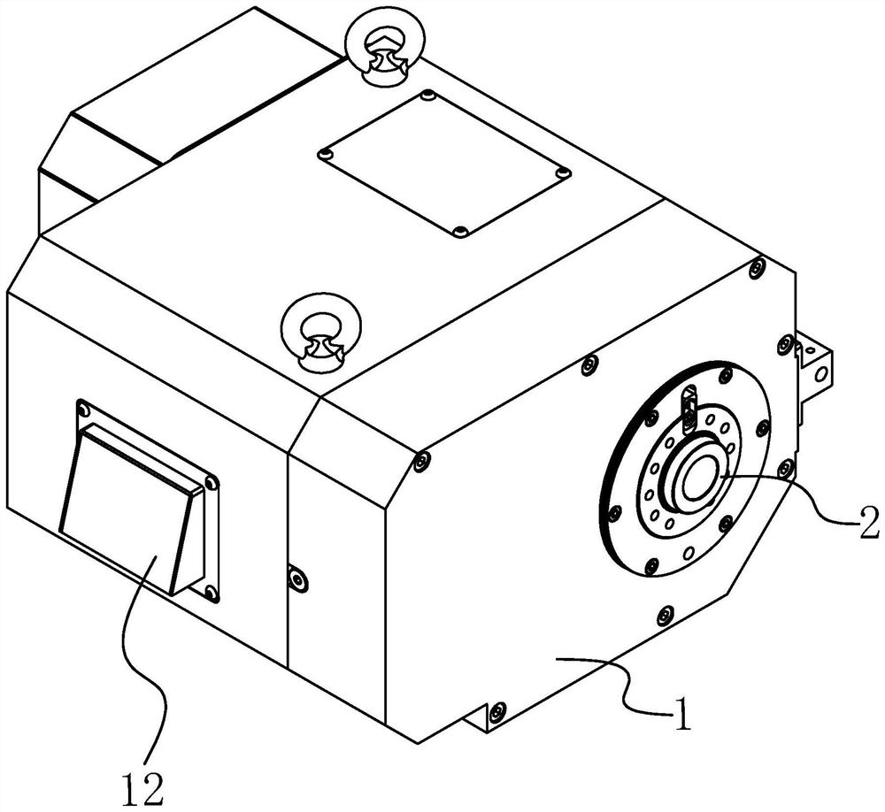
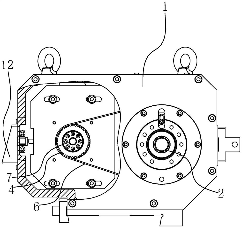
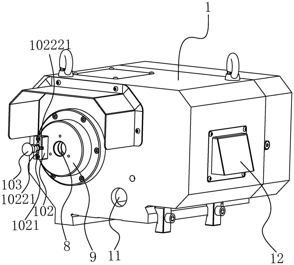
[0032] like Figure 1-5 As shown, the present invention includes a casing 1, a main shaft 2, a motor 3 is arranged in the casing 1, a motor synchronizing wheel 4 is arranged on the output shaft of the motor 3, a main shaft synchronizing wheel 5 is connected to the upper surface of the main shaft 2, and the main shaft synchronizing wheel 5 It is connected with the motor synchronous pulley 4 through the belt 6 .

[0033] The motor 3 drives the output shaft to drive the motor synchronous wheel 4 to rotate, the motor synchronous wheel 4 rotates to drive the belt 6 to drive, the belt 6 drives the spindle synchronous wheel 5 to rotate, the spindle synchronous wheel 5 rotates to drive the spindle 2 to rotate, and the motor 3 is arranged in the housing....


PUM


Abstract

The invention provides a high-precision headstock, which belongs to the technical field of machine tool processing equipment, and solves the problem that the headstock in the prior art has low transmission precision and cannot meet the high-precision requirements of certain shaft parts. The invention includes a housing, a main shaft, a motor inside the housing, a motor synchronous wheel on the output shaft of the motor, a main shaft synchronous wheel connected in the upper direction of the main shaft, and a belt connecting the main shaft synchronous wheel and the motor synchronous wheel. The invention improves the integrity of the head frame through the built-in motor, keeps it tidy, and ensures the transmission accuracy; the connection mode of the expansion sleeve and the belt ensures the transmission accuracy; the design of the front 4 and rear 2 bearings increases the support accuracy; through the front screw The point contact method between the front pressure ring and the rear screw and the rear pressure ring reduces the axial movement tolerance of the main shaft; through the fixed and active integrated mechanism, the conversion between the fixed core and the movable core of the main shaft is realized; The air hole and the air outlet provide continuous cooling to the motor to prevent the motor from overheating and affecting the accuracy.

Description

technical field [0001] The invention belongs to the technical field of machine tool processing equipment, and in particular relates to a machine tool headstock. Background technique [0002] The grinder is a grinder for processing the outer surface and the shoulder end face of the cylindrical, conical or other shape of the workpiece. and other major equipment in the industry. It is also suitable for the processing of shaft parts with small batches and high precision requirements in military, aerospace and general precision machining workshops. The cylindrical grinder is composed of a bed, a head frame, a car tail, a grinding head, a transmission vacuum device and other components. [0003] The headstock in the machine tool is an important part of the machine tool. The headstock of the prior art sets the motor outside the headstock, which accumulates dust and cannot be kept clean, resulting in low transmission accuracy and cannot meet the high requirements of some shaft par...

Claims


Application Information

Patent Timeline
Patent Type & Authority Patents(China)
IPC IPC(8): B24B41/02B24B47/12B24B41/04B24B55/00
CPCB24B41/02B24B47/12B24B41/04B24B55/00
Inventor 张佑刚
Owner ZHEJIANG QUANSHUN MACHINE TOOL
Why Eureka
Try Eureka