
Screw binding machine

A screw machine and screw technology, which is applied in binding and other directions, can solve the problems of high labor intensity for workers, small size of double-headed smooth screws, time-consuming and labor-intensive efficiency, etc., and achieve the effect of easy operation, reduced labor intensity, and reduced binding difficulty

Active Publication Date: 2021-11-19
深圳市鸿源文具有限公司
View PDF5 Cites 0 Cited by
  • Summary
  • Abstract
  • Description
  • Claims
  • Application Information

AI Technical Summary

Problems solved by technology

[0004] However, the double-headed smooth screws used for binding notebooks or papers are small in size, and it is difficult for workers to handle them when they are manually bound, so they are inserted into the pre-made notebook or paper screw holes.
And even if the worker puts the sub-nail and the female nail of the double-headed smooth screw into the screw hole for pre-positioning, but when screwing it in the next step, on the one hand, it must take care of fixing the screw at one end to prevent rotation, and on the other hand, it must fix the screw at the other end. The screw at one end exerts force to make the two screws screw together to make the notebook or paper binding firm. This traditional manual production method is time-consuming, labor-intensive, inefficient, and labor-intensive for workers.

Method used


Image

  • Screw binding machine
  • Screw binding machine
  • Screw binding machine

Examples


Embodiment Construction

[0023] The present invention will be described in detail below in conjunction with the accompanying drawings, and the technical solutions in the embodiments of the present invention will be clearly and completely described. Apparently, the described embodiments are only some, not all, embodiments of the present invention. Based on the embodiments of the present invention, all other embodiments obtained by persons of ordinary skill in the art without making creative efforts belong to the protection scope of the present invention.

[0024] It should be noted that when a component is said to be "fixed" to another component, it can be directly on the other component or there can also be an intervening component. When a component is said to be "connected" to another component, it may be directly connected to the other component or there may be intervening components at the same time. When a component is said to be "set on" another component, it can be set directly on the other comp...


PUM


Abstract

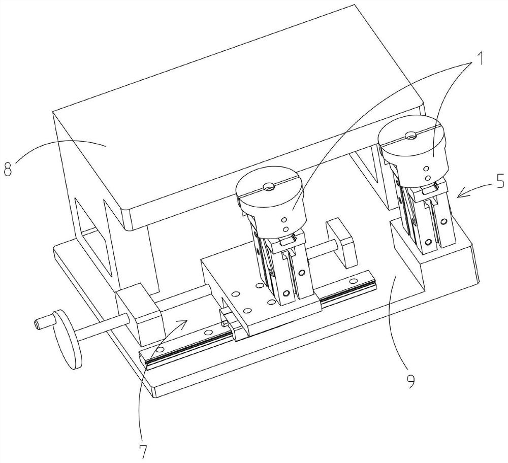
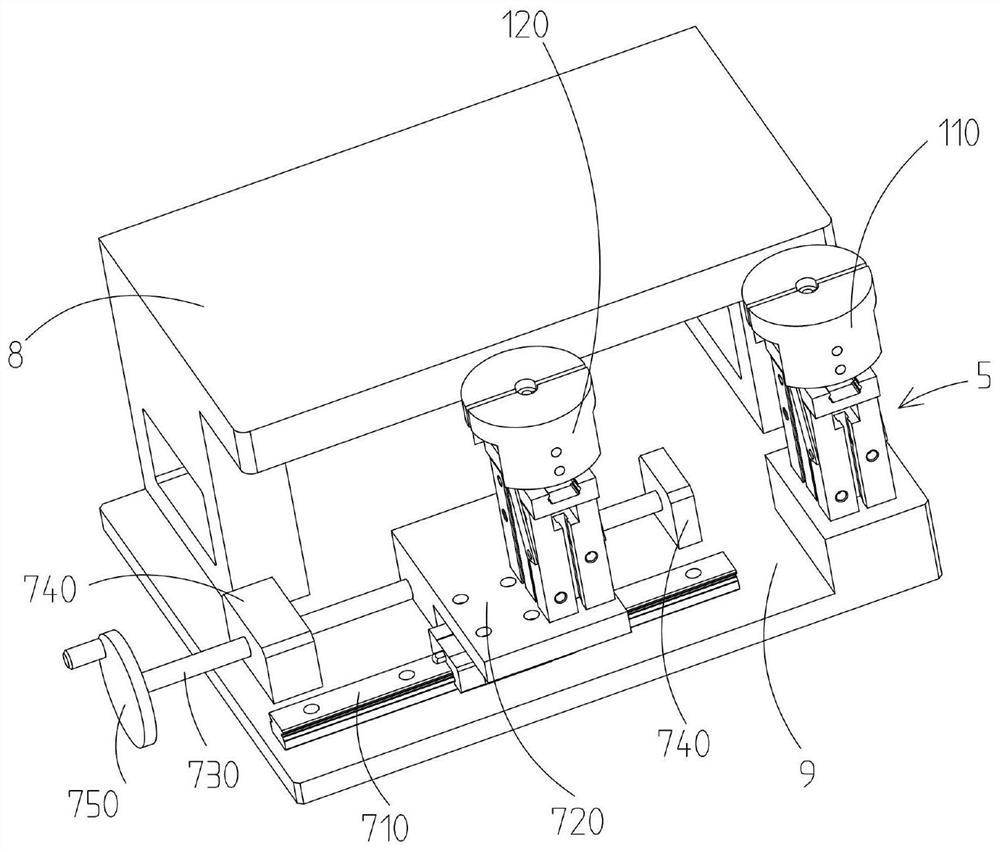
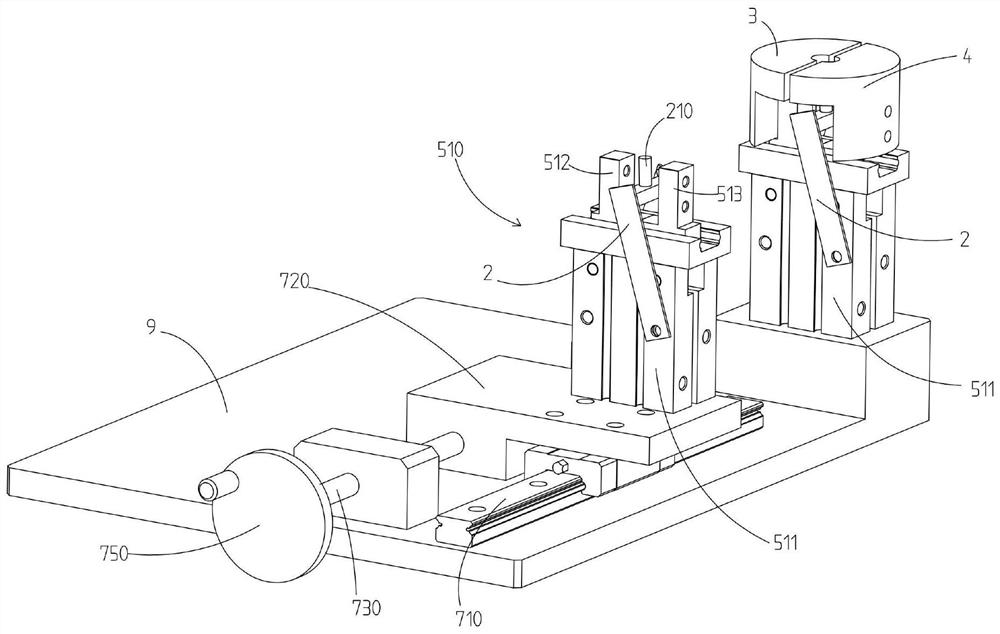
The invention discloses a screw binding machine. The screw binding machine comprises at least one screw containing base, and each screw containing base comprises a positioning magnetic base for adsorbing and positioning screws, a first clamping block, a second clamping block and a driving mechanism for driving the first clamping block and the second clamping block to relatively separate or close; the first clamping blocks and the second clamping blocks comprise containing grooves for clamping the screws when the clamping blocks are folded; the screw binding machine further comprises a position adjusting mechanism, the number of the screw containing bases is two, the first screw containing base is a fixed screw containing base, and the second screw containing base is a movable screw containing base; the position adjusting mechanism is connected with the movable screw containing base and used for adjusting the relative distance between the movable screw containing base and the fixed screw containing base; and the screw binding machine comprises a supporting platform, the supporting platform is adjacent to the screw containing bases, and the upper end face of the supporting platform is flush with that of the screw containing base. The screw binding machine provides an auxiliary machine for binding screws for notebooks or paper, so that the screws are bound more simply and conveniently, the productivity is improved, and the labor intensity of workers is reduced.

Description

technical field [0001] The present application relates to the technical field of book binding devices, in particular to a binding screw machine. Background technique [0002] It should be noted that the contents recorded in this section do not represent all prior art. [0003] When binding notebooks or papers, there are many ways, such as gluing, threading, threading, etc.; and binding notebooks or papers with screws is a more preferred one, which is reliable in connection and beautiful in appearance. The screws used for screw binding are generally The double-headed smooth screw is a sub-female screw without a twisting groove, and the screw head is a smooth end face, so after binding notebooks or papers with this double-headed smooth screw, the connection is still flat and not Create additional inconvenience to users. [0004] But the double-head smooth screw that is used for binding notebook or paper is small in size, and it is difficult for the worker to handle it when m...

Claims


Application Information

Patent Timeline
Patent Type & Authority Applications(China)
IPC IPC(8): B42B5/12B42B5/08
CPCB42B5/12B42B5/08
Inventor 刘耀许
Owner 深圳市鸿源文具有限公司
Learn More