Taping machine main shaft structure and its timing interruption control method

A technology of taping machine and main shaft, which is applied in the field of timing interruption control, can solve problems such as complex structure and inability to be adjusted independently, and achieve the effects of small transmission error, short transmission chain and fast response speed

Active Publication Date: 2022-02-08
江苏安澜万锦电子股份有限公司
View PDF0 Cites 0 Cited by
  • Summary
  • Abstract
  • Description
  • Claims
  • Application Information

AI Technical Summary

Problems solved by technology

In addition to the main transmission system of the taping device, some taping machines also arrange a separate transmission system for the tape unwinding device to provide power for the tape unwinding device, and the structure is complicated.
Winding and unwinding tensions are the same and cannot be adjusted individually

Method used


Image

  • Taping machine main shaft structure and its timing interruption control method
  • Taping machine main shaft structure and its timing interruption control method
  • Taping machine main shaft structure and its timing interruption control method

Examples


Embodiment Construction

[0035] The present invention will be described in further detail below in conjunction with the accompanying drawings.

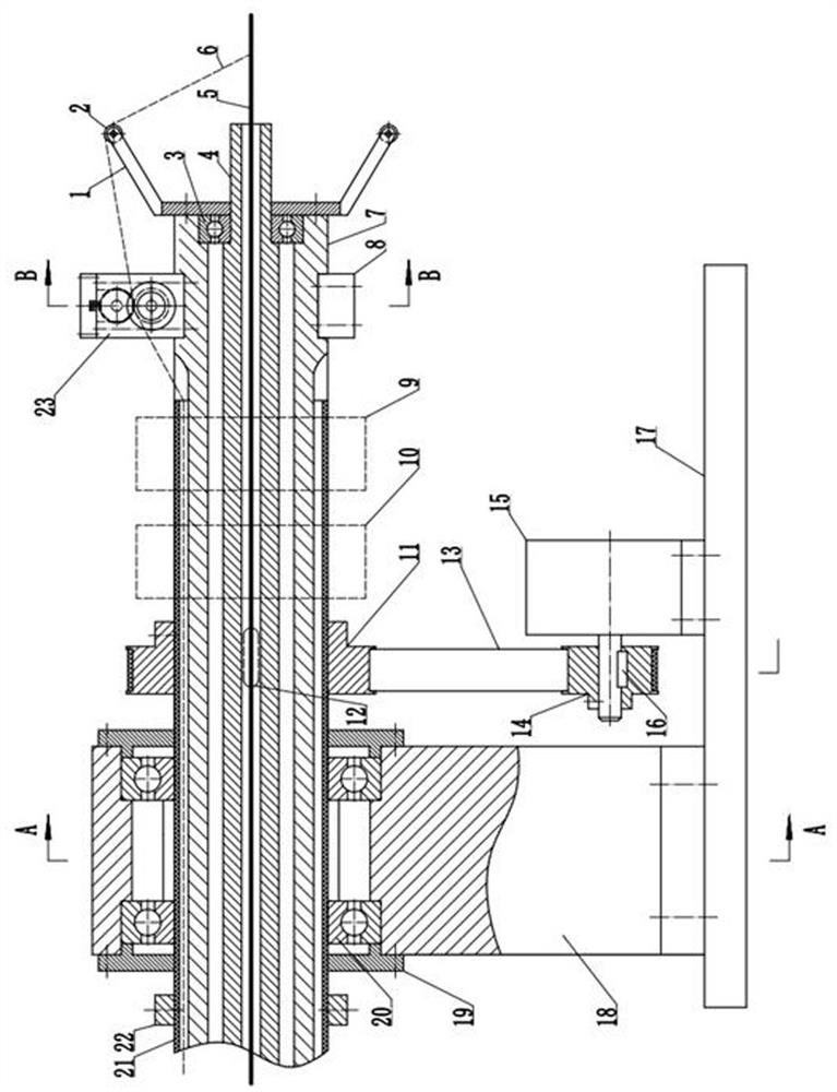
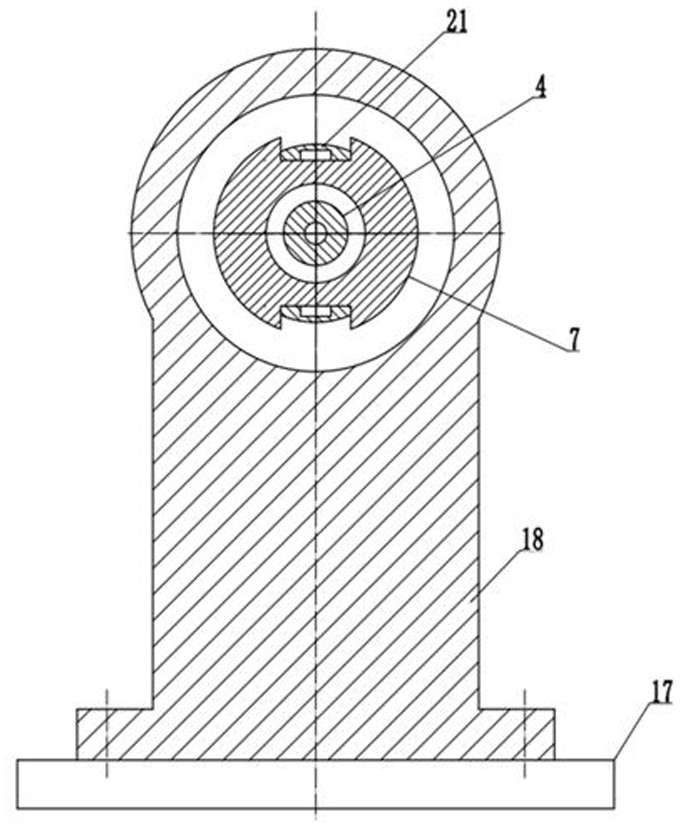
[0036] The main shaft structure of a kind of taping machine in this embodiment is as follows: figure 1 , figure 2 , image 3 Shown, this taping machine comprises base plate 17, main transmission device, tape feeding device 23 and taping device, wherein:

[0037] The main transmission device includes a main shaft 7 and a main shaft motor 15 . The main shaft 7 is mounted on the base plate 17 through the first bearing 20 , and the main shaft motor 15 is connected with the main shaft 7 for controlling the rotation of the main shaft 7 . An inner shaft 4 is installed inside the main shaft 7 through the second bearing 3, and the inner shaft 4 is a hollow structure for the wire 5 to pass through;

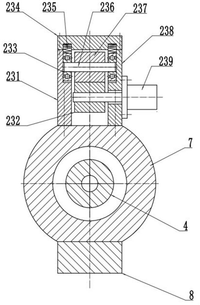
[0038] The tape feeding device 23 is installed on the main shaft 7 , and the tape feeding device includes a housing, a Mylar motor 239 , an upper roller 237 and a low...


PUM


Abstract

The invention discloses a main shaft structure of a taping machine and a timing interruption control method thereof. The spindle structure includes a base plate, a main transmission device, a tape feeding device and a tape wrapping device. The main shaft structure of the present invention adds a tape feeding device between the tape unwinding device and the tape winding device, so that the tape unwinding tension and the tape winding tension are independent of each other, and the winding tension can be adjusted independently; the Mylar motor directly drives the Mylar to move, and the transmission chain Short, transmission error is small; the rotation angle of the main shaft is measured by the rotary encoder, so as to accurately control the number of pulses sent to the Mylar motor driver, without cumulative error; the main shaft is directly measured by angular displacement, and the Mylar motor is controlled by angular position, which is better than the traditional The precision of speed measurement and speed control is higher, and the response speed is faster; through a timing interruption every several milliseconds, even if the rotation speed of the main shaft produces a large disturbance, the Mylar motor can follow the rotation of the main shaft in time to drive the Mylar to move, and Can be adjusted quantitatively.

Description

technical field [0001] The invention relates to a main shaft structure of a taping machine, in particular to a main shaft structure of a taping machine whose winding tension and unwinding tension can be adjusted independently of each other and a timing interruption control method thereof. Background technique [0002] The taping machine is mainly composed of a tape unwinding device and a tape winding device. The tape wrapping device is responsible for winding the material tape onto the core wire, and the tape unwinding device is responsible for outputting the tape material. The tape material is generally stored in the tape storage drum, and the tension of the tape release drives the tape storage drum to rotate to output the tape. In addition to the main drive system of the taping device, some taping machines also arrange a separate transmission system for the tape unwinding device to provide power for the tape unwinding device, and the structure is complicated. Winding tens...

Claims


Application Information

Patent Timeline
Patent Type & Authority Patents(China)
IPC IPC(8): B65H59/38
Inventor 叶辉周建运燕启叶沪伟杨小斌丁仕燕
Owner 江苏安澜万锦电子股份有限公司
Why Eureka
Try Eureka