Pouring equipment and pouring ladle

A pouring ladle and equipment technology, applied in casting equipment, metal processing equipment, casting molten material container, etc., can solve problems such as molten iron cannot be kept at constant speed, economic loss, and affect the accuracy of the encoder, so as to reduce transmission error and uniform pouring Hot metal, the effect of improving production efficiency

Active Publication Date: 2012-10-03
XINXING DUCTILE IRON PIPES CO LTD
View PDF5 Cites 5 Cited by
  • Summary
  • Abstract
  • Description
  • Claims
  • Application Information

AI Technical Summary

Problems solved by technology

[0002] The pouring system and the control method of the pouring system are the key components and steps in the production process of metal pipe casting. In the actual production process, in order to ensure the pouring quality, the pouring system must pour molten iron into the centrifuge at a constant speed during the pouring process, even if The flow rate of molten iron pouring is constant, otherwise it will cause uneven wall thickness of the cast iron pipe produced, produce unqualified products, and bring economic losses to the enterprise. Whether the pouring system can be poured at a uniform speed depends on the structure of the casting ladle and the driving of the pouring ladle Action of the device
[0003] Chinese invention patent document CN101912954A discloses a pouring system capable of constant-velocity pouring. In this pouring system, a fan-shaped pouring ladle is used, and the oil cylinder directly drives the fan-shaped pouring ladle. An angular displacement encoder is installed on the rotating shaft of the pouring ladle to measure the pouring ladle. The angle of rotation is fed back to the control part, and the control part calculates and adjusts the moving speed of the oil cylinder according to the feedback angle signal to ensure that the fan-shaped pouring ladle rotates at a constant speed to achieve uniform pouring. In this pouring equipment, the angular displacement encoder is set on the rotating shaft of the pouring ladle , because the rotating shaft of the ladle is located near the gate of the molten iron, the temperature is very high, and vibration may occur during the rotation of the ladle, both high temperature and vibration will affect the accuracy of the encoder and affect the working life of the encoder, resulting in the molten iron not the Chinese utility model patent document CN2313689Y also discloses a pouring system that can realize constant velocity pouring. Constant velocity plate, the hydraulic cylinder drives the constant velocity plate through the pulley mechanism, and the constant velocity movement of the hydraulic cylinder drives the fan-shaped pouring bag to rotate at the same speed through the constant velocity plate to achieve uniform pouring. This pouring device has many components and complex structure. The constant velocity plate Although there is rolling friction with the pulley mechanism, the constant velocity plate and the pulley mechanism are easy to wear or get stuck after a period of use, causing molten iron to not flow out of the fan-shaped casting ladle at a constant velocity; there is also a pouring equipment disclosed in the Soviet patent document SU326021A. In the pouring equipment, the fan-shaped side of the fan-shaped ladle is connected to a connecting line, which is driven by an oil cylinder through a moving pulley. In the case of a constant speed of the oil cylinder, the connecting line moves at a constant speed twice the speed of the oil cylinder, and the fan-shaped ladle is connected Driven by the line, it rotates at a constant speed to achieve uniform pouring, but there are too many mechanical transmission equipment in this pouring equipment, and these mechanical transmission equipment work in an environment of high temperature, strong vibration and dust, and the mechanical transmission equipment is affected by the working environment. The impact will produce a large transmission error, resulting in molten iron not flowing out of the fan-shaped ladle at a uniform speed

Method used


Image

  • Pouring equipment and pouring ladle
  • Pouring equipment and pouring ladle
  • Pouring equipment and pouring ladle

Examples


Embodiment Construction

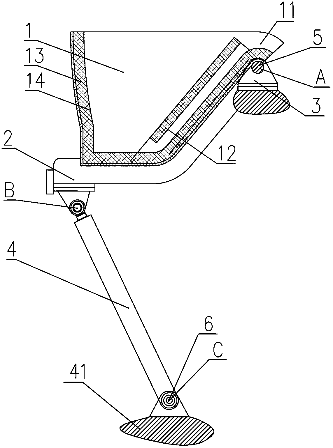
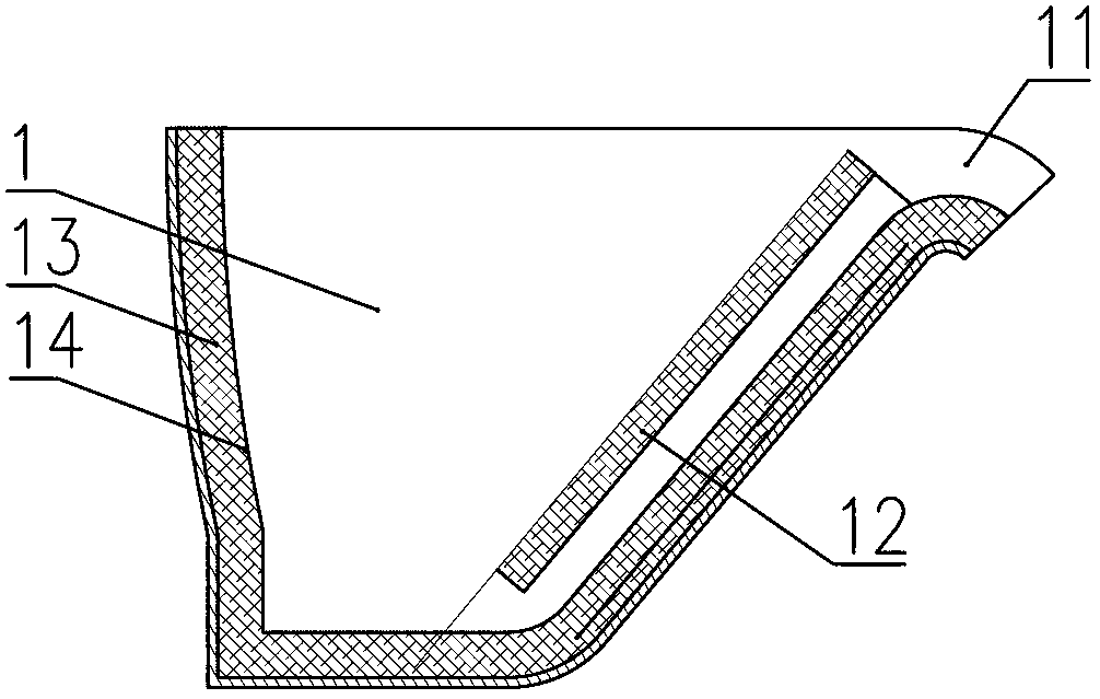
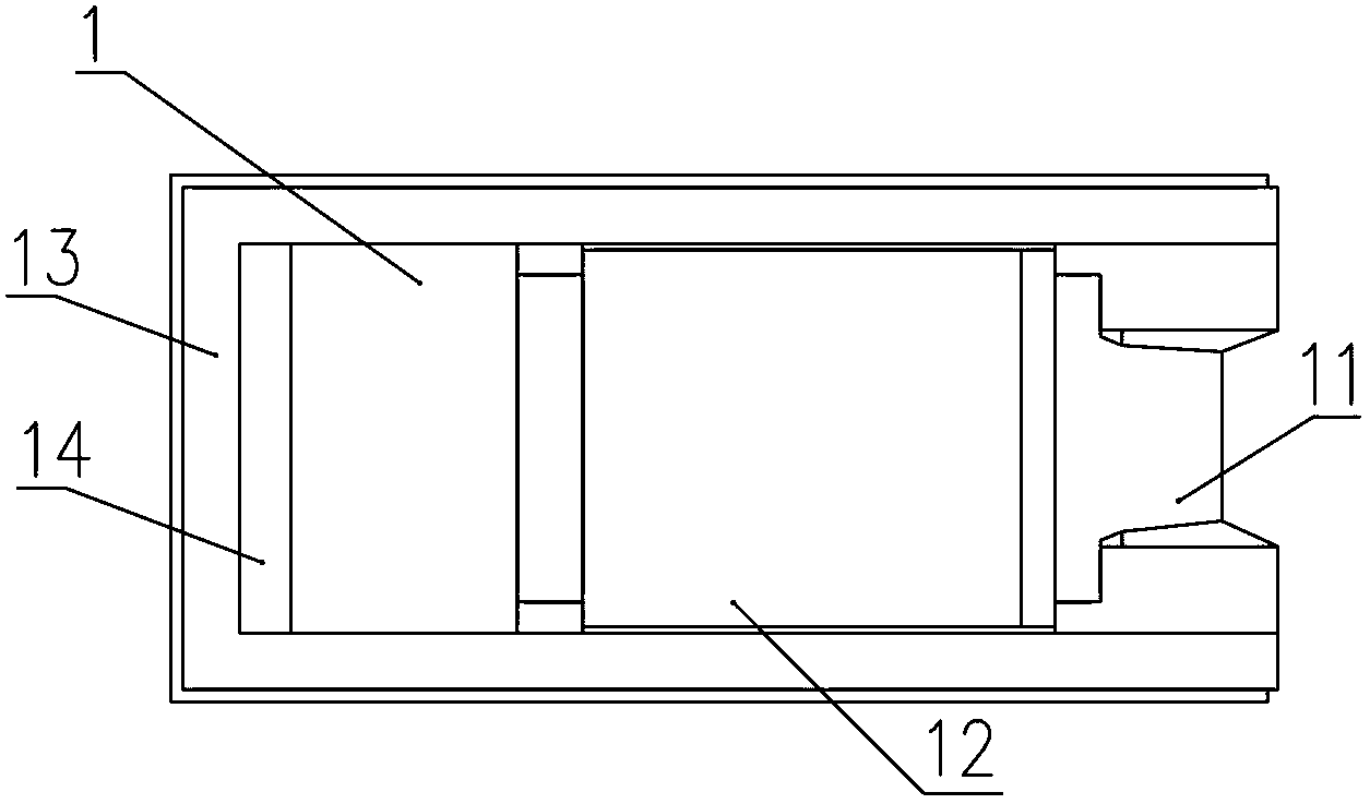
[0025] Such as figure 1 , 2 , 3, the pouring equipment includes a pouring ladle 1, a pouring ladle frame 2, a fixed support body 3, a hydraulic cylinder 4, and a hydraulic cylinder base 41. The pouring ladle 1 is fixed on the pouring ladle frame 2, and one end of the pouring ladle frame 2 passes through the first The rotating shaft 5 is hinged on the fixed support body 3, the right end of the pouring ladle 1 is provided with a gate 11, the first rotating shaft 5 is located at a position close to the gate 11, and one end of the hydraulic cylinder 4 is hinged on the casting ladle frame 2 away from the first The bottom of one end of the rotating shaft 5 and the other end are hinged on the hydraulic cylinder base 41 through the second rotating shaft 6. The hydraulic cylinder 4 is provided with a linear displacement digital encoder connected to the controller, and the linear displacement digital encoder The displacement of the hydraulic cylinder 4 can be detected in real time and ...


PUM


Abstract

The invention provides pouring equipment and a pouring ladle. The pouring equipment comprises the pouring ladle, a pouring ladle frame, a fixed supporting body, a hydraulic cylinder and a hydraulic cylinder base, wherein the pouring ladle is fixed on the pouring ladle frame; one end of the hydraulic cylinder is hinged on the pouring ladle frame; and the other end of the hydraulic cylinder is hinged on the hydraulic cylinder base, wherein one end of the pouring ladle frame is arranged on the fixed supporting body; the right end of the pouring ladle is provided with a pouring gate; the width of an upper opening of the pouring ladle is a fixed value; the internal side of the left side wall of the pouring ladle, which is far away from the pouring gate, is provided with a compensating curved plane; the hydraulic cylinder moves at a constant speed; and in the pouring process, the compensating curved plane can be used for compensating angular velocity variation of the pouring ladle, so that the pouring flow speed of the pouring ladle is constant. According to the pouring equipment provided by the invention, when the hydraulic cylinder moves at the constant speed, the final pouring flow speed of the pouring ladle, which is invariable at the fixed value, is ensured; the quality of a cast is effectively guaranteed; and meanwhile, as a driving device has a simple structure and less transmission parts, lower fault rate is achieved and the production efficiency is effectively increased.

Description

technical field [0001] The invention relates to a casting melt container, in particular to a casting melt container without a heating device. Background technique [0002] The pouring system and the control method of the pouring system are the key components and steps in the production process of metal pipe casting. In the actual production process, in order to ensure the pouring quality, the pouring system must pour molten iron into the centrifuge at a constant speed during the pouring process, even if The flow rate of molten iron pouring is constant, otherwise it will cause uneven wall thickness of the cast iron pipe produced, produce unqualified products, and bring economic losses to the enterprise. Whether the pouring system can be poured at a uniform speed depends on the structure of the casting ladle and the driving of the pouring ladle device action. [0003] Chinese invention patent document CN101912954A discloses a pouring system capable of constant-velocity pourin...

Claims


Application Information

Patent Timeline
Patent Type & Authority Applications(China)
IPC IPC(8): B22D13/10B22D13/12B22D41/00
Inventor 张同波李军习杰周波李九狮檀鹤青刘俊锋闫现臣李国前张国生温海军王亚飞
Owner XINXING DUCTILE IRON PIPES CO LTD
Why Eureka
Try Eureka