Optical system and head-mounted display device

An optical system and light technology, applied in optics, optical components, instruments, etc., can solve the problems of insufficient light resolution, difficult light analysis and processing, and blurred image edges.

Active Publication Date: 2021-11-19
GOERTEK OPTICAL TECH CO LTD
View PDF6 Cites 1 Cited by
  • Summary
  • Abstract
  • Description
  • Claims
  • Application Information

AI Technical Summary

Problems solved by technology

[0003] Based on this, in view of the lack of resolution of light in current head-mounted display devices, it is difficult to fully complete the analysis of light, and it is easy to cause blurred edge

Method used


Image

  • Optical system and head-mounted display device
  • Optical system and head-mounted display device
  • Optical system and head-mounted display device

Examples


Embodiment Construction

[0032] The following will clearly and completely describe the technical solutions in the embodiments of the present invention with reference to the accompanying drawings in the embodiments of the present invention. Obviously, the described embodiments are only part of the embodiments of the present invention, not all of them. Based on the embodiments of the present invention, all other embodiments obtained by persons of ordinary skill in the art without creative efforts fall within the protection scope of the present invention.

[0033] It should be noted that all directional indications (such as up, down, left, right, front, back...) in the embodiments of the present invention are only used to explain the relationship between the components in a certain posture (as shown in the accompanying drawings). Relative positional relationship, movement conditions, etc., if the specific posture changes, the directional indication will also change accordingly.

[0034] In addition, in t...


PUM


Abstract

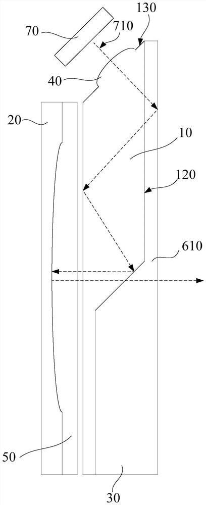
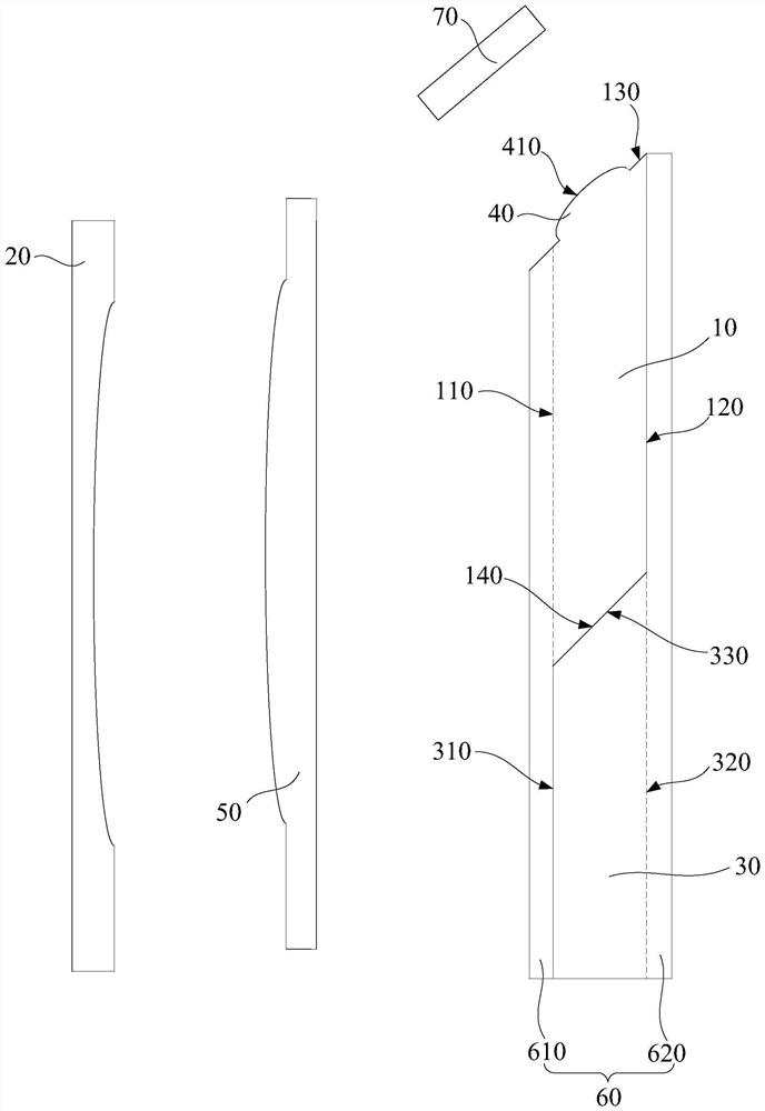
The invention discloses an optical system and a head-mounted display device. The optical system comprises a first lens which is provided with a first surface and a second surface which are oppositely arranged, wherein the first lens further comprises a light coupling-in end face, and the light coupling-in end face is connected to the first surface and the second surface; a polarization reflector is arranged on the side, away from the light coupling-in end face, of the first lens; a light splitting lens is arranged on one side of the first surface of the first lens; a correction lens is arranged on the side, away from the light coupling-in end face, of the first lens and used for correcting aberration, and the polarization reflector is arranged between the first lens and the correction lens; an analysis lens is arranged on one side of the light coupling-in end face of the first lens, one side of the analysis lens deviating from the first lens is a light incidence face, and the light incidence face of the analysis lens is a free-form surface or an aspheric surface. According to the optical system, the light resolution can be improved, so the marginal definition of an imaging picture is improved.

Description

technical field [0001] The invention relates to the technical field of optical display, in particular to an optical system and a head-mounted display device. Background technique [0002] A head mounted display device (Head Mount Display) can provide users with an immersive virtual screen experience. A display unit is provided in the head-mounted display device, and the size of the display unit is relatively small. Therefore, the light emitted by the display unit needs to be analyzed and enlarged. However, in order to reduce the volume of the head-mounted display device, the waveguide is usually used to complete the transmission of light. Since the thickness of the waveguide itself is relatively thin, the resolution of the light is insufficient, especially at the edge of the image, it is difficult to fully complete the transmission of light. Analytical processing can easily lead to blurred edges of the imaged image. Contents of the invention [0003] Based on this, it is...

Claims


Application Information

Patent Timeline
IPC IPC(8): G02B27/01
CPCG02B27/0172
Inventor 刘风磊杨春赵博刚胡守岩
Owner GOERTEK OPTICAL TECH CO LTD
Why Eureka
Try Eureka