Unmanned aerial vehicle no-fly zone and electronic fence control method and system, equipment and medium

A technology of electronic fence and control method, which is applied in the direction of three-dimensional position/channel control, etc., can solve the problems of unfavorable development and maintenance of separate design, achieve high engineering application significance, facilitate maintenance, and reduce task burden

Pending Publication Date: 2021-11-19
PRODRONE TECH (SHENZHEN) CO LTD
View PDF0 Cites 0 Cited by
  • Summary
  • Abstract
  • Description
  • Claims
  • Application Information

AI Technical Summary

Problems solved by technology

Second, from the perspective of the algorithm itself, the properties of the no-fly zone and the electronic fence are basically similar, and the separate design is not conducive to later development and maintenance

Method used


Image

  • Unmanned aerial vehicle no-fly zone and electronic fence control method and system, equipment and medium
  • Unmanned aerial vehicle no-fly zone and electronic fence control method and system, equipment and medium
  • Unmanned aerial vehicle no-fly zone and electronic fence control method and system, equipment and medium

Examples


Embodiment Construction

[0037] In order to make the object, technical solution and advantages of the present invention clearer, the present invention will be described in further detail below in conjunction with the accompanying drawings and embodiments. It should be understood that the specific embodiments described here are only used to explain the present invention, not to limit the present invention.

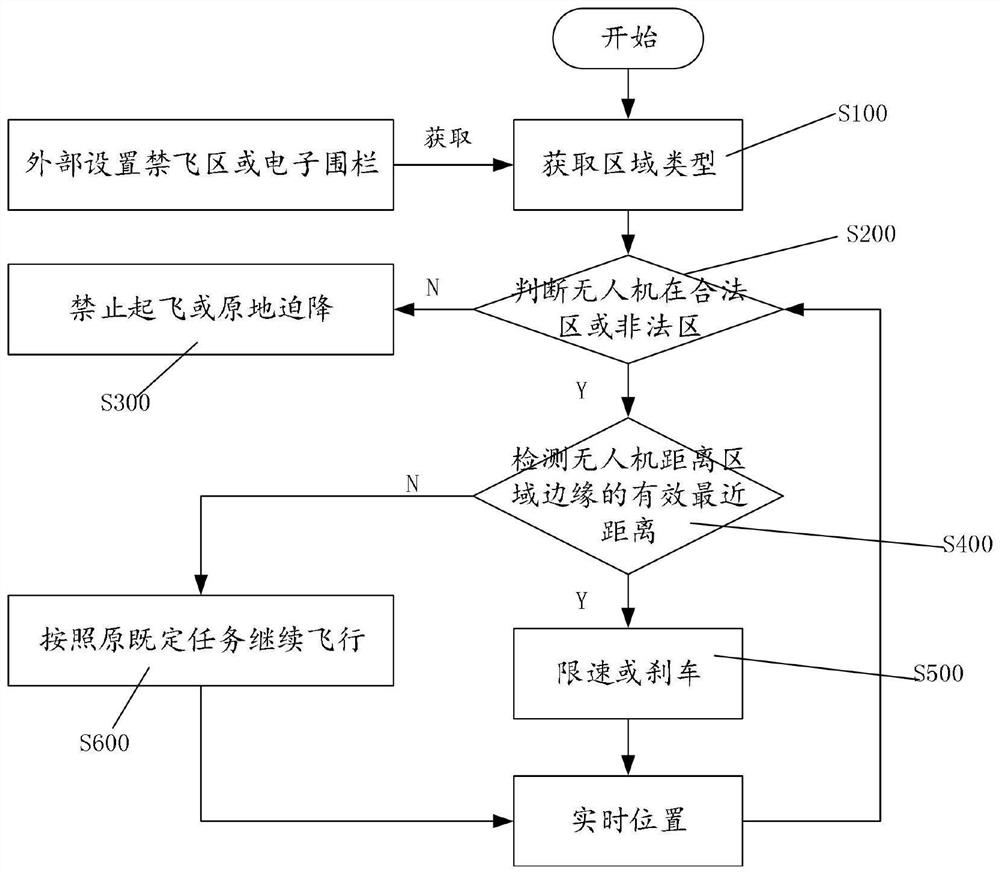
[0038] In the current UAV flight control algorithm, the no-fly zone control strategy and the electronic fence control strategy are usually separated and executed separately. Although this single separation strategy reduces the coupling very well and is simple and clear in form; but in terms of flight control efficiency, first, it increases the burden on the flight control, and the flight control needs to run two separate sets of algorithm strategies at the same time. Because the area where the aircraft is at any time is a no-fly zone or an electronic fence, the two cannot be taken together. Second...


PUM


Abstract

The invention is suitable for the field of rotor unmanned aerial vehicles, and provides an unmanned aerial vehicle no-fly zone and electronic fence control method and system, equipment and a medium. The method comprises the following steps: acquiring a zone type, and judging whether an unmanned aerial vehicle is in a legal zone or an illegal zone based on the zone type; when the UAV is in the illegal area, prohibiting the UAV from taking off or landing the UAV in situ; when the UAV is in the legal area, detecting the effective nearest distance between the UAV and the edge of the area in real time; when the UAV is close to the edge of the area, subjecting the UAV to speed limiting or braking; and when the UAV is not close to the edge of the area, enabling the UAV to continue to fly according to the original established task. According to the embodiment of the invention, the UAV can cope with the no-fly zone or the electronic fence freely, the no-fly zone and the electronic fence function of the unmanned aerial vehicle are integrated, online comprehensive detection analysis, comprehensive management and comprehensive control are realized, and later comprehensive maintenance is also realized.

Description

technical field [0001] Embodiments of the present invention belong to the field of rotor unmanned aerial vehicles, and in particular relate to control methods, systems, equipment and media for unmanned aerial vehicle no-fly zones and electronic fences. Background technique [0002] A no-fly zone is a specific area defined by a country or region where aircraft are prohibited from flying. Drones entering the no-fly zone will seriously threaten aviation safety. Therefore, for multi-rotor UAVs, corresponding flight control measures must be taken to prevent them from entering the no-fly zone. [0003] Correspondingly, the electronic fence is a functional area defined and established by the user in order to perform tasks within a specific range, and the drone must perform tasks in this area. Such as plant protection machine for field spraying, surveying machine for regional mapping and so on. For the electronic fence, the flight control must also be designed so that the drone ca...

Claims


Application Information

Patent Timeline
Patent Type & Authority Applications(China)
IPC IPC(8): G05D1/10
CPCG05D1/106
Inventor 黄立李旭林家民王龙洪亮薛源刘华斌
Owner PRODRONE TECH (SHENZHEN) CO LTD
Why Eureka
Try Eureka