Telescopic pipe for electric cleaner

A technology of vacuum cleaners and telescopic tubes, applied in the direction of suction hoses, suction nozzles, etc., can solve the problems of telescopic spring disconnection and difficult operation, and achieve the effect of preventing disconnection and preventing disconnection of connecting parts

Inactive Publication Date: 2004-02-04
SANYO ELECTRIC CO LTD
View PDF0 Cites 0 Cited by
  • Summary
  • Abstract
  • Description
  • Claims
  • Application Information

AI Technical Summary

Problems solved by technology

At this time, the expansion and contraction will bend the expansion spring, and there will be a large stress on the bending part, which may cause the expansion spring to break.
Moreover, there is also a problem that it is difficult to assemble the second sleeve holding the lead wire into the tube.

Method used


Image

  • Telescopic pipe for electric cleaner
  • Telescopic pipe for electric cleaner
  • Telescopic pipe for electric cleaner

Examples


Embodiment Construction

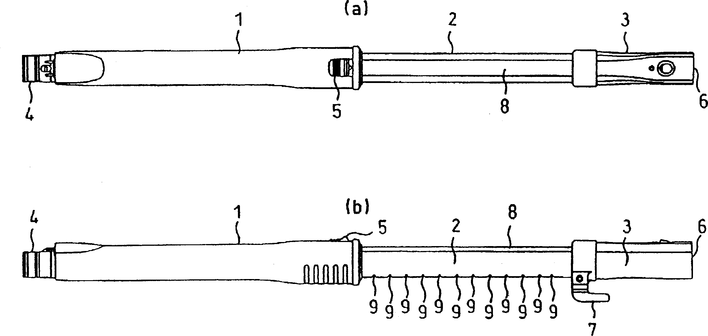
[0048] Below, refer to the attached figure 1 Embodiments of the present invention will be described.

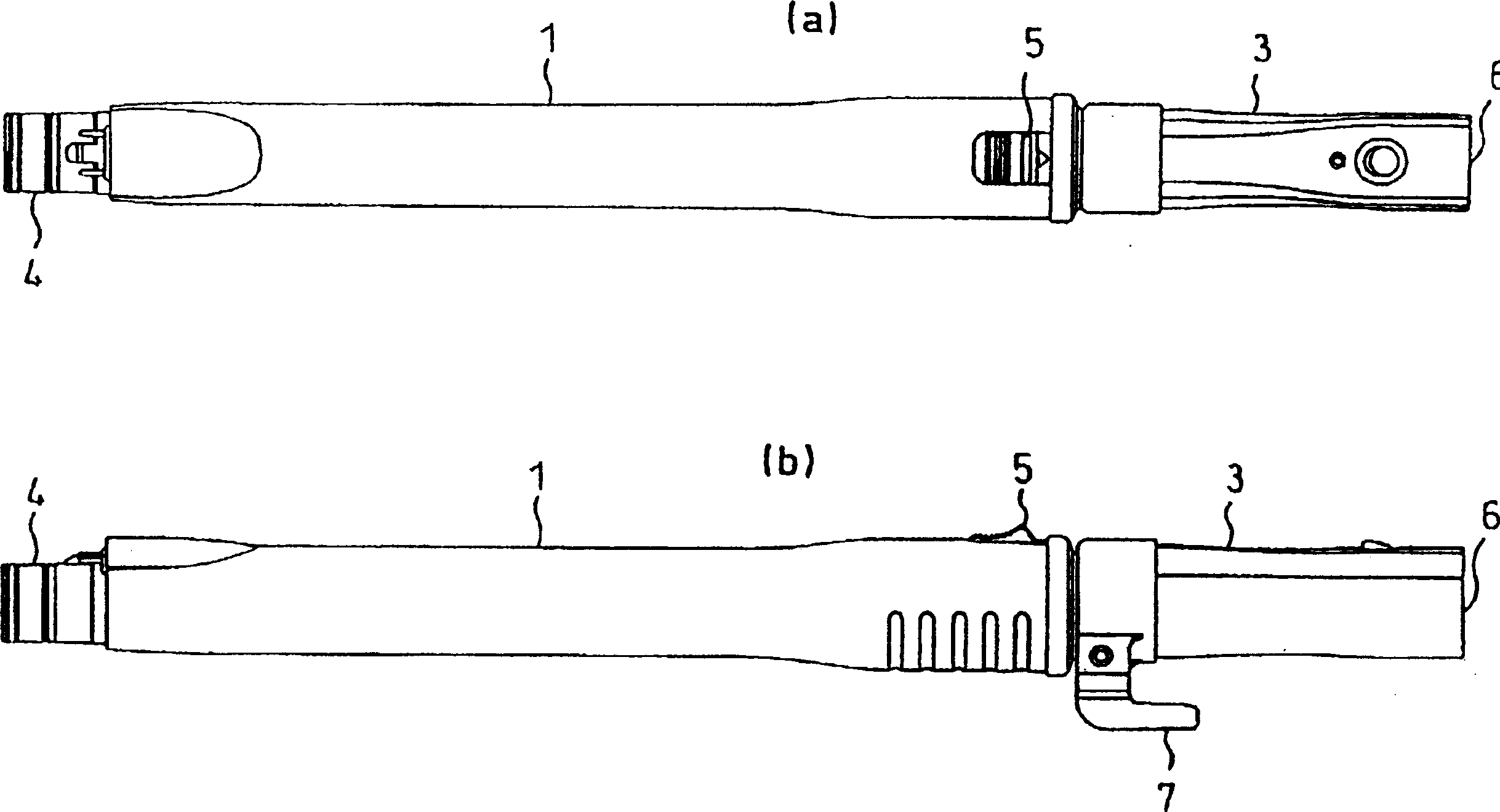
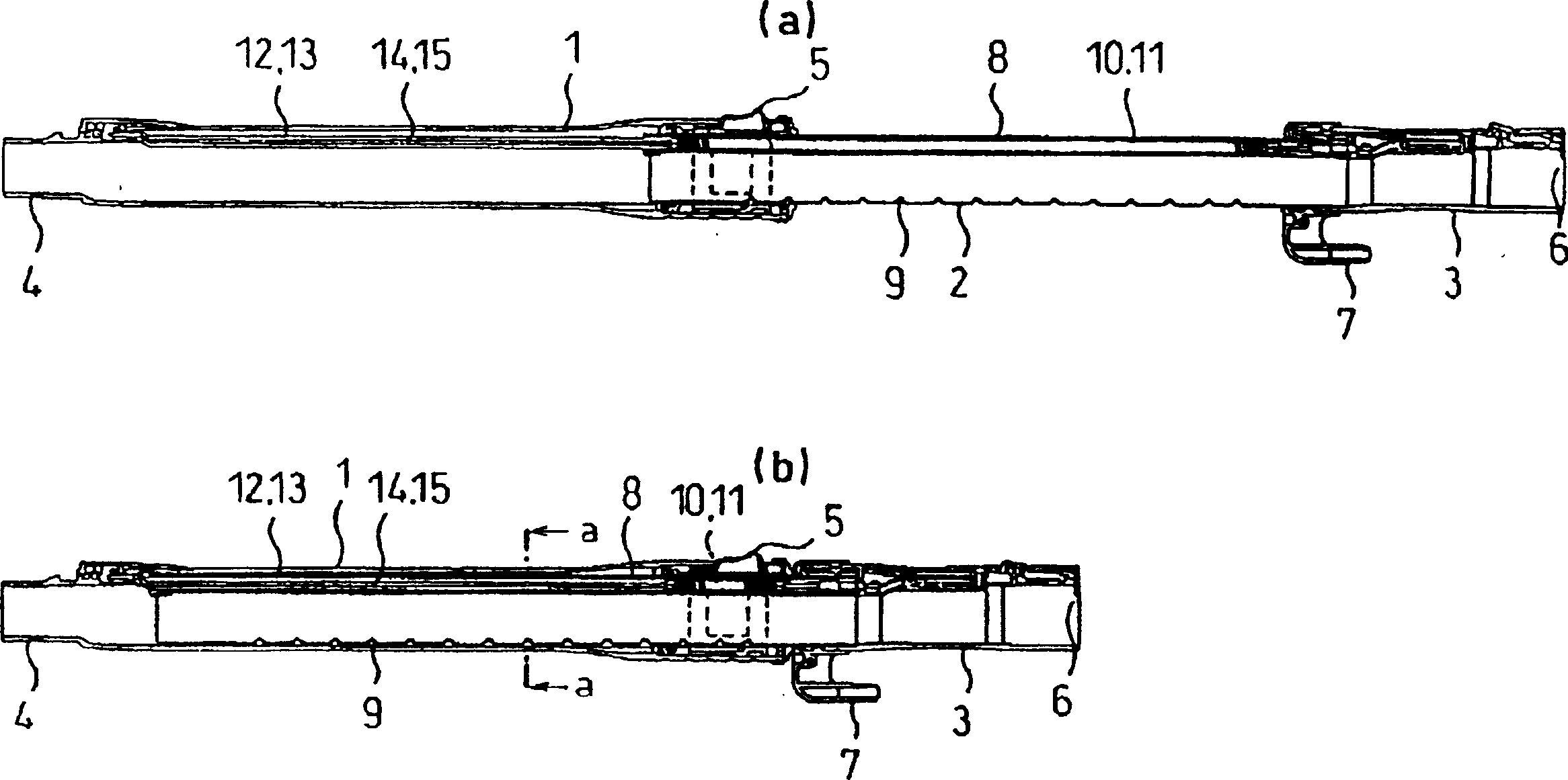
[0049] figure 1 (a), (b) and figure 2 (a), (b) show the telescoping tube of the electric vacuum cleaner which is one embodiment of this invention.

[0050] The telescopic tube generally includes an outer tube 1 connected to the side of the electric vacuum cleaner body (not shown), and a connecting member 3 connected to an electric brush (not shown) of the suction device, and communicates with the outer tube 1 The inner tube 2 of the connecting member 3; the inner tube 2 is in the state of being able to enter and exit the outer tube 1, and is fixed at an appropriate protruding position.

[0051] The outer tube 1 is provided with a connection part 4 for connecting to the main body side, and an operation part 5 for understanding the operation of the fitting state of the outer tube 1 and the inner tube 2, and a connection part 3 is formed for connecting to the electric brush ...


PUM


Abstract

Disclosed is an extension tube of the electric dust collector, which is arranged between a pipe installation port of the electric dust collector body and a suction use electric brush. The invention includes an inner pipe which is contained in an outer pipe and can freely go in and out of the outer pipe, an adjustment mechanism for adjusting the protruding amount of the inner pipe, and a wiring mechanism. The invention is characterized in that the wiring mechanism is provided with a first sleeve, an extension spring which can be extensibly contained in the first sleeve, a lead cover part which can cover one end of the extension spring, and a second sleeve which can be freely glidingly arranged in the first sleeve. The invention can prolong the service life of the spring and can prevent bad connections of the interlink part of the down-leads.

Description

【Technical field】 [0001] The present invention relates to a telescoping tube of an electric vacuum cleaner interposed between a tube installation opening of a main body of the electric vacuum cleaner and a power brush for suction. 【Background technique】 [0002] It is well known in the prior art that as a telescoping tube of an electric vacuum cleaner equipped with an electric brush for suction, an inner tube is provided on the outer tube so that it can be moved in and out freely, and the length of the inner tube protruding from the outer tube is adjusted to lock the telescopic tube. [0003] This conventional device can be used to drive the wiring mechanism of the power supply used by the electric brush to form a telescopic spring that can change the length along with the inner tube and the outer tube. [0004] However, in this conventional device, the spring load when the telescopic spring expands or contracts, or the rotational force generated with the expansion and contr...

Claims


Application Information

Patent Timeline
Patent Type & Authority Patents(China)
IPC IPC(8): A47L9/24A47L9/02
Inventor 吉见和好米田勲
Owner SANYO ELECTRIC CO LTD
Why Eureka
Try Eureka