Oil drainage connector of transformer and transformer

A technology of oil drain joint and transformer, applied in transformer/inductor housing, transformer/inductor cooling, etc., can solve the problem of time-consuming and other issues

Pending Publication Date: 2021-11-23
SIEMENS TRANSFORMER WUHAN
View PDF0 Cites 0 Cited by
  • Summary
  • Abstract
  • Description
  • Claims
  • Application Information

AI Technical Summary

Problems solved by technology

[0002] The oil drain joint of the transformer is usually equipped with a metal sealing plate at the end to avoid oil leakage. The metal sealing plate is fixed with bolts. When emergency oil draining is required, the bolts must be unscrewed one by one and the metal sealing plate removed, which is time-consuming

Method used


Image

  • Oil drainage connector of transformer and transformer
  • Oil drainage connector of transformer and transformer
  • Oil drainage connector of transformer and transformer

Examples


Embodiment Construction

[0031] In order to have a clearer understanding of the technical features, purposes and effects of the invention, the specific embodiments of the present invention are now described with reference to the accompanying drawings, in which the same reference numerals represent components with the same or similar structures but the same functions.

[0032] In this article, "schematic" means "serving as an example, example or illustration", and any illustration or implementation described as "schematic" should not be interpreted as a more preferred or more advantageous Technical solutions.

[0033] In order to make the drawing concise, each drawing only schematically shows the parts related to the present invention, and they do not represent the actual structure of the product.

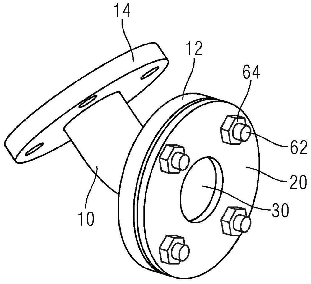
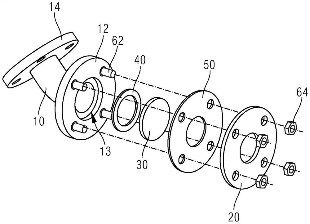
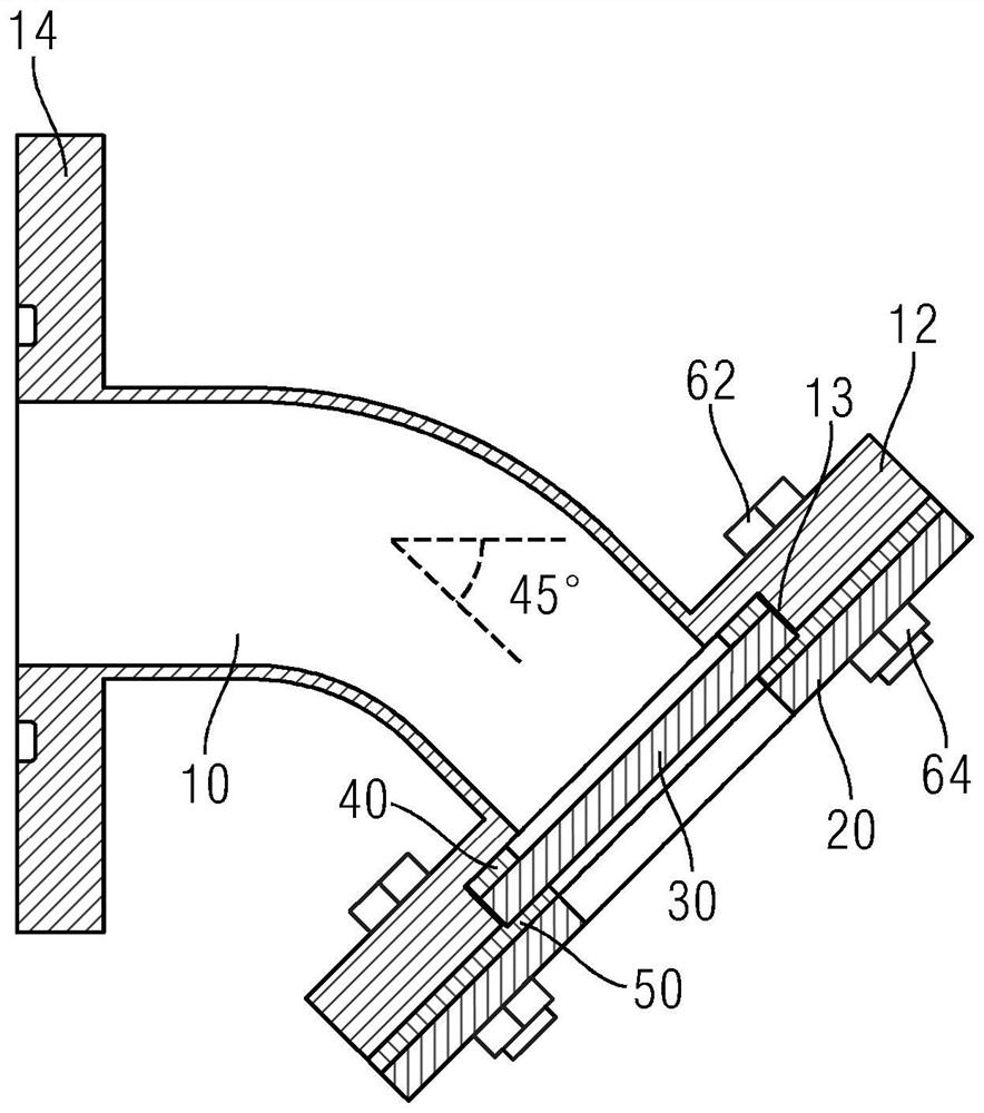
[0034] figure 1 It is a structural schematic diagram of an exemplary embodiment of an oil drain joint. figure 2 It is an exploded schematic diagram of the oil drain joint of the transformer. refer to f...


PUM


Abstract

The invention provides an oil drainage connector of a transformer. The oil drainage connector comprises an oil pipe (10), a cover plate (20) and a glass sealing plate (30). One end of the oil pipe is provided with a first flange (12), and the other end of the oil pipe is connected with an oil tank of the transformer. The cover plate is in a circular ring shape, and the cover plate is coaxially installed on the first flange. The glass sealing plate is clamped between the first flange and the cover plate and can cover the pipe opening of the oil pipe and the inner circle of the cover plate, and the pipe opening of the oil pipe and the inner circle of the cover plate can be communicated by breaking the glass sealing plate within the range of the inner circle of the cover plate. The oil drainage joint of the transformer can be quickly opened during emergency oil drainage. The invention further provides the transformer with the oil drainage connector.

Description

technical field [0001] The invention relates to an oil drain joint, in particular to an oil drain joint for a transformer. The invention also relates to a transformer having the above-mentioned oil drain connection. Background technique [0002] The oil drain joint of the transformer is usually equipped with a metal sealing plate at the end to avoid oil leakage. The metal sealing plate is fixed with bolts. When emergency oil draining is required, the bolts must be unscrewed one by one and the metal sealing plate removed, which is time-consuming. Contents of the invention [0003] The purpose of the present invention is to provide an oil drain joint of a transformer, which can be quickly opened when oil is drained in an emergency. [0004] Another object of the present invention is to provide a transformer whose oil drain joint can be quickly opened during emergency oil drain. [0005] The invention provides an oil discharge joint of a transformer, which comprises an oil ...

Claims


Application Information

Patent Timeline
Patent Type & Authority Applications(China)
IPC IPC(8): H01F27/02H01F27/12
Inventor 黄先博吴先威张亚旭廖威周灿文朱德虎刘欢王其珏
Owner SIEMENS TRANSFORMER WUHAN
Why Eureka
Try Eureka