Eureka AIR delivers breakthrough ideas for toughest innovation challenges, trusted by R&D personnel around the world.

Array substrate and display panel

An array substrate, thin film transistor technology, applied in optics, instruments, electrical components, etc., can solve problems such as easy to appear shaking head pattern, and achieve the effect of improving voltage difference, reducing the risk of shaking head pattern, and improving brightness difference

Pending Publication Date: 2021-11-23
TCL CHINA STAR OPTOELECTRONICS TECH CO LTD
View PDF0 Cites 1 Cited by
  • Summary
  • Abstract
  • Description
  • Claims
  • Application Information

AI Technical Summary

Problems solved by technology

[0002] During the research and practice of the existing technology, the inventor of the present application found that the display panel is prone to shaking head problems under the Stripper architecture

Method used


Image

  • Array substrate and display panel
  • Array substrate and display panel
  • Array substrate and display panel

Examples


Embodiment Construction

[0037] The following will clearly and completely describe the technical solutions in the embodiments of the application with reference to the drawings in the embodiments of the application. Apparently, the described embodiments are only some of the embodiments of the application, not all of them. Based on the embodiments in this application, all other embodiments obtained by those skilled in the art without making creative efforts belong to the scope of protection of this application. In addition, it should be understood that the specific implementations described here are only used to illustrate and explain the present application, and are not intended to limit the present application. In this application, unless stated to the contrary, the used orientation words such as "up" and "down" usually refer to up and down in the actual use or working state of the device, specifically the direction of the drawing in the drawings ; while "inside" and "outside" refer to the outline of ...


PUM


Abstract

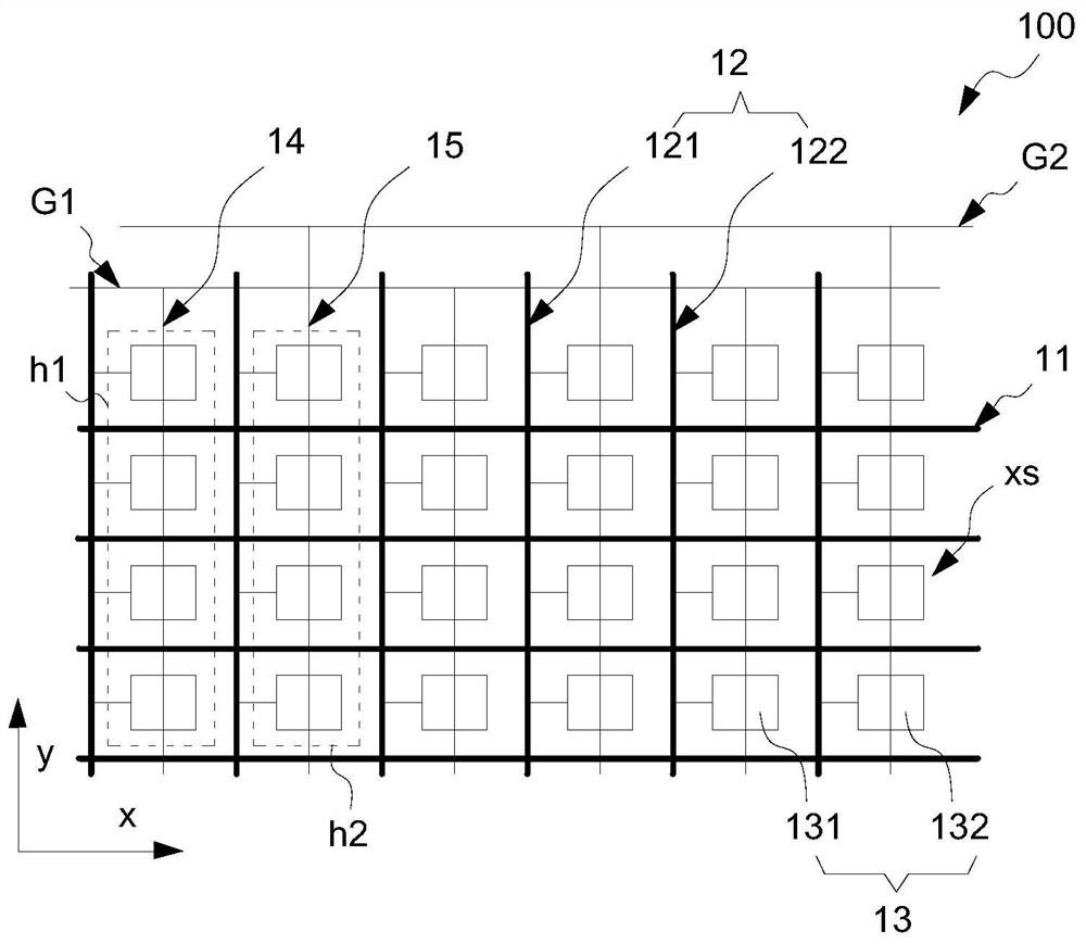
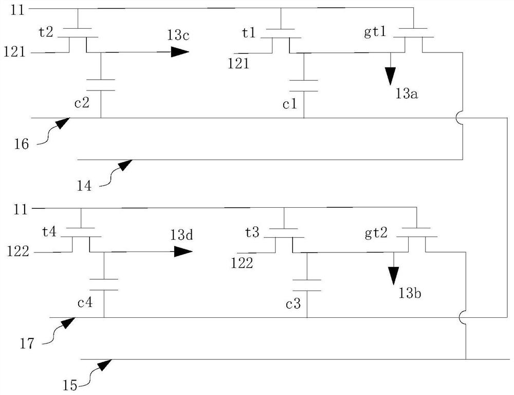
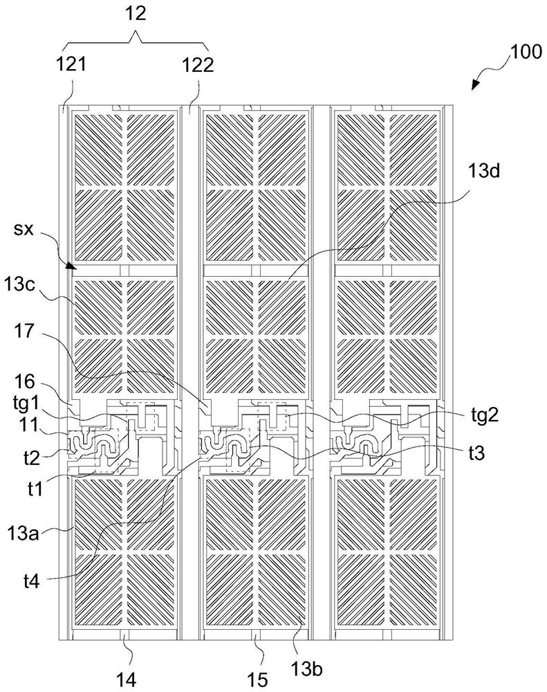
The embodiment of the invention discloses an array substrate and a display panel. In the same picture frame, one of first data lines or second data lines are used for accessing positive polarity signals, and the other of the first data lines and the second data lines are used for accessing negative polarity signals; first pixel electrodes are electrically connected to the first data lines, and second pixel electrodes are electrically connected to the second data lines; first shared electrodes are used for accessing signals with the same polarity as the first data lines, and first sub-pixel electrodes are connected to the first shared electrodes through first shared thin film transistors; and second shared electrodes are used for accessing signals with the same polarity as the second data lines, and second sub-pixel electrodes are connected to the second shared electrodes through second shared thin film transistors. According to the embodiment of the invention, the voltage difference between the first sub-pixel electrodes and the second sub-pixel electrodes is improved, so that the brightness difference between the pixels corresponding to the first pixel electrodes and the pixels corresponding to the second pixel electrodes in the same picture frame reduces the risk of shaking lines.

Description

technical field [0001] The present application relates to the field of display technology, in particular to an array substrate and a display panel. Background technique [0002] During the research and practice of the prior art, the inventors of the present application found that the display panel is prone to shaking head problems under the Stripper architecture. Specifically, different columns, because of different polarities and different brightness, there will be a problem of vertical lines appearing with the movement of people's sight. The lower the frequency, the lower the resolution of the panel, and the greater the polarity difference between positive and negative frames relative to the common electrode The larger the size, the more serious the phenomenon of shaking the head. Contents of the invention [0003] Embodiments of the present application provide an array substrate and a display panel, which can reduce the risk of shaking head lines. [0004] An embodime...

Claims


Application Information

Patent Timeline
IPC IPC(8): H01L27/12H01L27/32G02F1/1343G02F1/1362G02F1/1368
CPCH01L27/1214G02F1/1362G02F1/136213G02F1/134309G02F1/1368H10K59/123H01L27/124
Inventor 吕晓文赵丽
Owner TCL CHINA STAR OPTOELECTRONICS TECH CO LTD
Why Eureka
Eureka Blog
Learn More