
Heat preservation belt winding equipment for petroleum conveying pipeline

A technology for oil conveying and thermal insulation belts, which is applied to devices and coatings that apply liquid to the surface. The effect of installation

Pending Publication Date: 2021-11-26
安徽胜方工程技术有限公司
View PDF12 Cites 2 Cited by
  • Summary
  • Abstract
  • Description
  • Claims
  • Application Information

AI Technical Summary

Problems solved by technology

[0005] 1. In real life, the insulation tape wrapped outside the oil pipeline needs to be updated and maintained when it is damaged by wind and sun, and the above-mentioned public documents need to pass the pipeline through the middle of the winding device, and the pipeline installed and in use It cannot pass through the winding device; therefore, only the pipes that have not been installed can be wrapped with insulation tape, and the pipes that have been installed and used cannot be wrapped with insulation tape, and the scope of use is small;
[0006] 2. When winding the insulation belt, it is necessary to add glue to the roller, and the roller is set on the turret through the winding mechanism. The turret rotates continuously during work, so it is inconvenient to add glue. At the same time, the glue has a certain viscosity , the glue cannot be continuously and automatically exported under the action of gravity, which makes the glue application effect not good enough, which affects the winding effect and service life of the insulation belt

Method used


Image

  • Heat preservation belt winding equipment for petroleum conveying pipeline
  • Heat preservation belt winding equipment for petroleum conveying pipeline
  • Heat preservation belt winding equipment for petroleum conveying pipeline

Examples


Embodiment 1

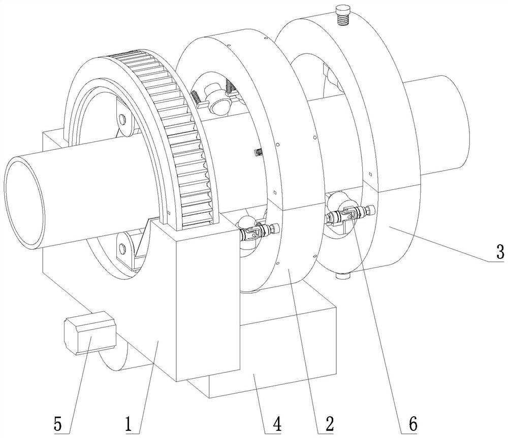
[0040] Such as figure 1 As shown, the present invention proposes a thermal insulation tape winding device for oil pipelines, including a winding assembly 1, a glue assembly 2 and a connecting assembly 6;

[0041] The winding assembly 1 is provided with an automatic glue-feeding assembly 4, the glue-making assembly 2 is connected with the winding assembly 1 through the connection assembly 6, and the glue-making assembly 2 is connected with the automatic glue-feeding assembly 4; the moving assembly 3 is connected with the glue-making assembly through the connection assembly 6 2 connections;

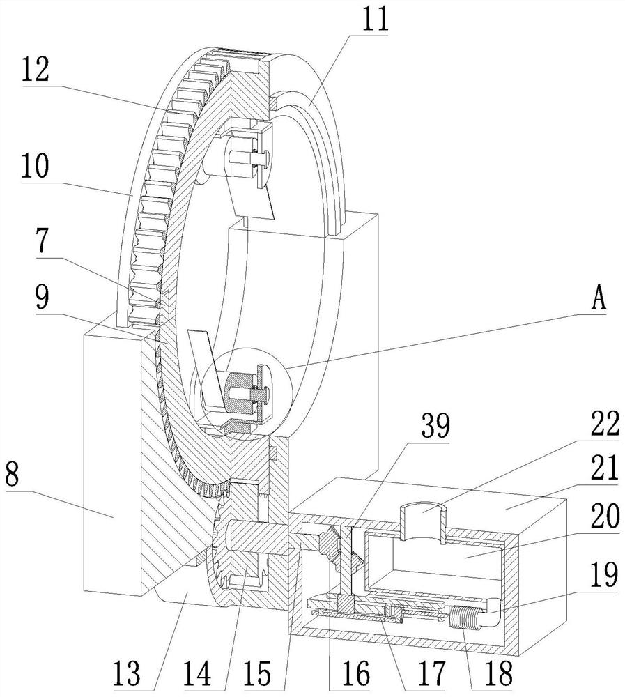
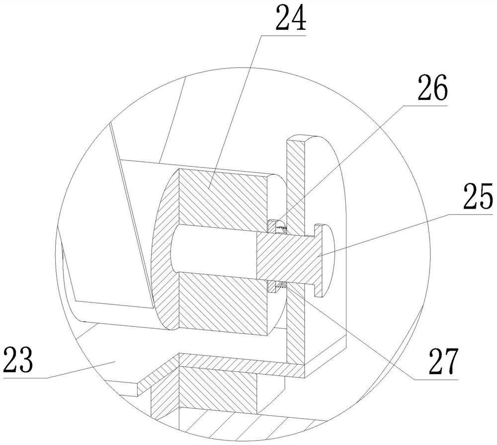
[0042] Such as Figure 2-3 As shown, the winding assembly 1 includes a locking member 7, a fixed seat 8, an upper fixed fan ring-9, a lower fixed fan ring-10, a fixed cover 13 and a gear 14; the fixed seat 8 is provided with a fan-shaped through groove, and the upper fixed fan ring The ring one 9 and the lower fixed fan ring one 10 are connected by two sets of locking parts 7; the upper f...

Embodiment 2

[0047] Compared with Embodiment 1, the present invention proposes a thermal insulation tape winding device for petroleum pipelines. The difference between this embodiment and Embodiment 1 is as follows: figure 2 with Figure 9 As shown, the automatic glue feeding assembly 4 includes a connection key 15, a transmission assembly 16, an air bag 18, a connecting pipe 19, a storage box 20 and a fixed box 21; the fixed box 21 is arranged on the fixed seat 8, and on the fixed box 21 A reciprocating device 17 is provided; the connecting key 15 is rotatably arranged on the fixed box 21 and connected with the rotating shaft of the gear 14, and the rotating shaft 39 is rotatably arranged on the fixed box 21 and connected with the reciprocating device 17, and the connecting key 15 and the rotating shaft 39 pass through the transmission Components 16 are connected by transmission; the storage box 20 is arranged on the fixed box 21, and the storage box 20 is provided with a connecting pipe...

Embodiment 3

[0052] Compared with Embodiment 1 or Embodiment 2, the thermal insulation tape winding equipment for petroleum pipeline proposed by the present invention has the following differences: figure 1 with Figure 5 As shown, it also includes a moving assembly 3; the moving assembly 3 is connected to the glue assembly 2 through a connecting assembly 6; wherein, the moving assembly 3 includes an upper fixed fan ring three 33, a lower fixed fan ring three 34 and a motor two 37; the upper fixed fan ring One end of the ring three 33 and the lower fixed fan ring three 34 is connected by hinge rotation, and the other end is connected by the locking member 7; the upper fixed fan ring three 33 and the lower fixed fan ring three 34 are all slidably connected with the second fixed frame 35, and Fixing frame two 35 is provided with threaded hole; Upper fixed fan ring three 33 and lower fixed fan ring three 34 are all provided with adjusting screw 38, and adjusting screw 38 is respectively conne...


PUM


Abstract

The invention relates to the technical field of pipeline maintenance equipment, in particular to heat preservation belt winding equipment for a petroleum conveying pipeline. The heat preservation belt winding equipment comprises a winding assembly, a gluing assembly, a moving assembly and a connecting assembly; an automatic glue feeding assembly is arranged on the winding assembly, the gluing assembly is connected with the winding assembly through the connecting assembly, and the gluing assembly is connected with the automatic glue feeding assembly; a motor I is arranged on a fixing cover; a gear is rotatably arranged on the fixing cover and is connected with a rotating shaft of the motor I; an upper fixing sector ring I and a lower fixing sector ring I are connected through two sets of locking pieces, are in sliding connection with a fixing seat through mounting sector rings and are in meshing transmission connection with the gear through gear teeth; and limiting pieces are slidably arranged on a fixing frame I, and a material roller is slidably connected with the limiting pieces and located between the two sets of limiting pieces. By means of the heat preservation belt winding equipment, the pipeline can be conveniently subjected to heat preservation belt winding installation after being installed and used, glue is automatically conveyed, automatic movement can be achieved, higher convenience and flexibility are achieved, the application range is wide, and the practicability is high.

Description

technical field [0001] The invention relates to the technical field of pipeline maintenance equipment, in particular to a thermal insulation tape winding equipment used for oil pipelines. Background technique [0002] In the actual development process of our country, petrochemical industry is a basic industry. Petroleum transportation pipelines mainly transport petroleum and liquid chemical raw materials, but the pipelines often have problems of corrosion and poor thermal insulation performance. Therefore, in order to improve the use of petrochemical pipelines In terms of efficiency and safety, advanced anti-corrosion and thermal insulation technology should be used reasonably to carry out management work, prolong the service life of pipelines, improve the reliability and effectiveness of overall management work, and lay a solid foundation for its subsequent development. [0003] The existing Chinese patent application number CN202010416305.6 discloses a winding processing m...

Claims


Application Information

Patent Timeline
Patent Type & Authority Applications(China)
IPC IPC(8): B65H81/02B05C1/04
CPCB65H81/02B05C1/04Y02P70/10
Inventor 王本军
Owner 安徽胜方工程技术有限公司
Learn More