Replaceable adhesive tape and its application method

A replaceable, adhesive strip technology, applied in the direction of winding strips, shafts and bearings, layered products, etc., to achieve the effect of saving production costs

Inactive Publication Date: 2007-04-25
宋宝三
View PDF3 Cites 1 Cited by
  • Summary
  • Abstract
  • Description
  • Claims
  • Application Information

AI Technical Summary

Problems solved by technology

Although the above-mentioned technologies have improved the performance of the rubber cartridge to varying degrees, they still cannot solve the problem of having to replace the whole rubber cartridge due to local damage.

Method used


Image

  • Replaceable adhesive tape and its application method
  • Replaceable adhesive tape and its application method
  • Replaceable adhesive tape and its application method

Examples


Embodiment Construction

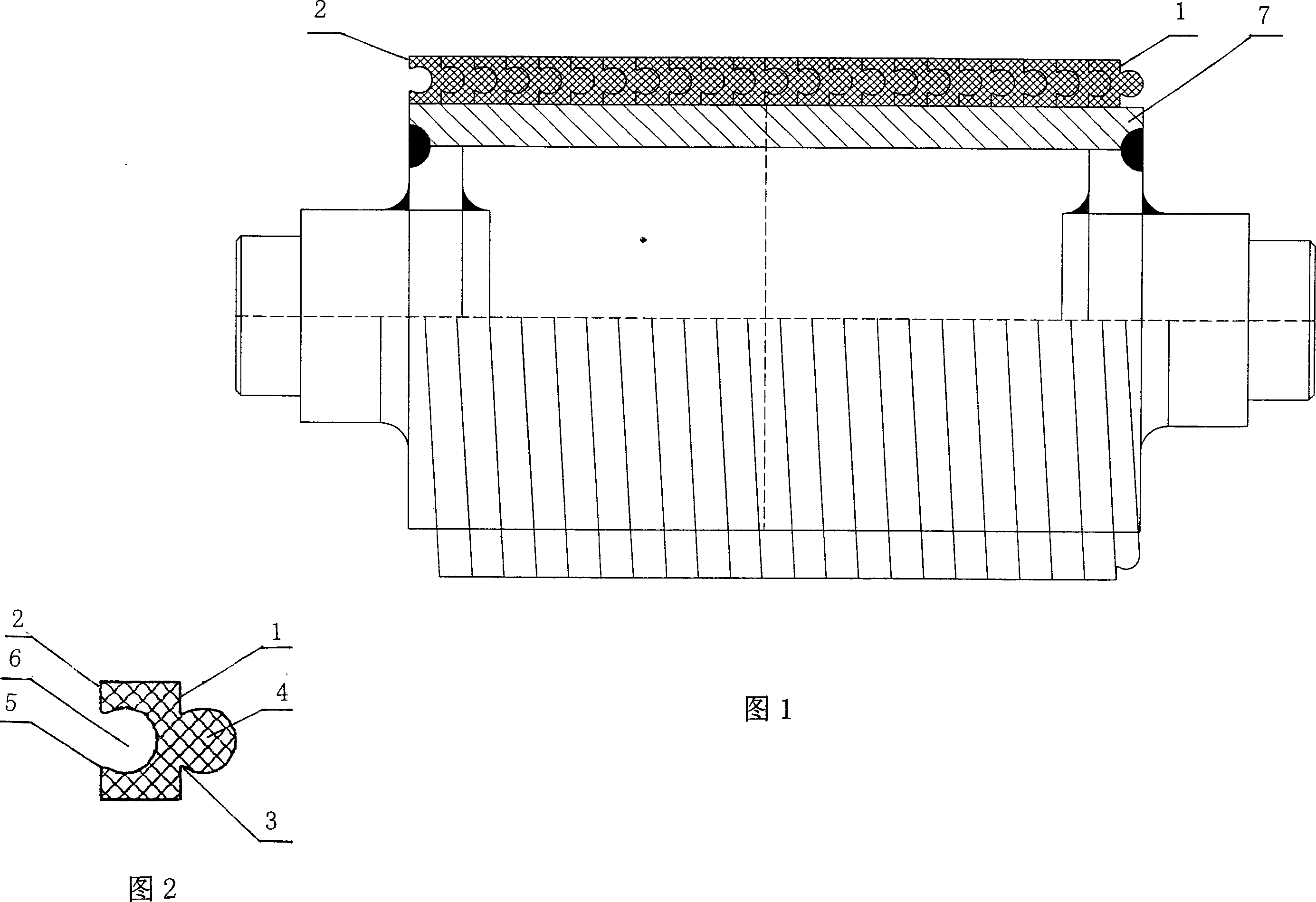
[0018] In Fig. 1, on the outer diameter of the rubber roller mandrel 7, there are beading strips closely arranged in a helical shape. The left and right convex surfaces 1 and concave surfaces 2 of the cross section of the beading strips are Ω-shaped with the same projection, and the cross section of the beading strips is parallel to each other. The beginning and end of the beading strip are fixedly bonded on the outer surface of the mandrel 7 . Beading strip also can be fixed on the outer surface of mandrel 7 with nail or by screw. The root 3 of the Ω-shaped protrusion and the entrance 5 of the Ω-shaped groove are smaller than the front 4 of the Ω-shaped protrusion and the inside 6 of the Ω-shaped groove, so the adjacent beading strips have a self-locking function during work, which can resist It will not crack under the action of external force. To facilitate winding, the root 3 of the protrusion and the entrance 5 of the groove on the convex surface 1 may be slightly small...


PUM


Abstract

The invention relates to an exchangeable compression rubber bar and relative operation. Wherein, the section of bar have concave and convex surfaces with same left and right projections; the convex root and groove inlet of convex surface are smaller tan the front of convex and the inner space of groove; the upper and lower surfaces of section are parallel; the bar is screw on the outer diameter of spindle of rubber roller; the convex is embedded into the groove of nearby rubber bar.

Description

(1) Technical field [0001] The present invention relates to the improvement of rubber cylinders on the surface of rubber rollers such as packaging machinery, textile machinery, printing machinery and woodworking machinery, and more precisely relates to a replaceable bead and its application method. (2) Background technology [0002] At present, the traditional rubber roller is wrapped with a layer of rubber cylinder on the rubber roller mandrel. In actual work, the surface of the rubber roller is easy to be worn, because the original shape and size of the rubber roller are changed after the rubber roller is worn, which directly affects the transportation. The accuracy and precision of the material requires frequent replacement of the rubber cartridge, and no matter how large the damaged surface is, it must be replaced as a whole. In order to prolong the service life of the rubber sleeve, people increase the hardness of the rubber sleeve on the surface of the rubber roller, b...

Claims


Application Information

Patent Timeline
Patent Type & Authority Applications(China)
IPC IPC(8): B65G39/02B65H27/00F16C13/00B32B1/08B65H81/00
Inventor 宋宝三
Owner 宋宝三
Why Eureka
Try Eureka