Full-automatic airtight connector O-shaped ring assembling equipment
A technology for assembling equipment and O-rings, applied in metal processing equipment, metal processing, manufacturing tools, etc., can solve problems such as quality not reaching uniform standards, speed not reaching customers, and slow rhythm, etc., to meet mass production Demand, reduced labor and production costs, and high degree of automation
- Summary
- Abstract
- Description
- Claims
- Application Information
AI Technical Summary
Problems solved by technology
Method used
Image

Examples
Embodiment 1
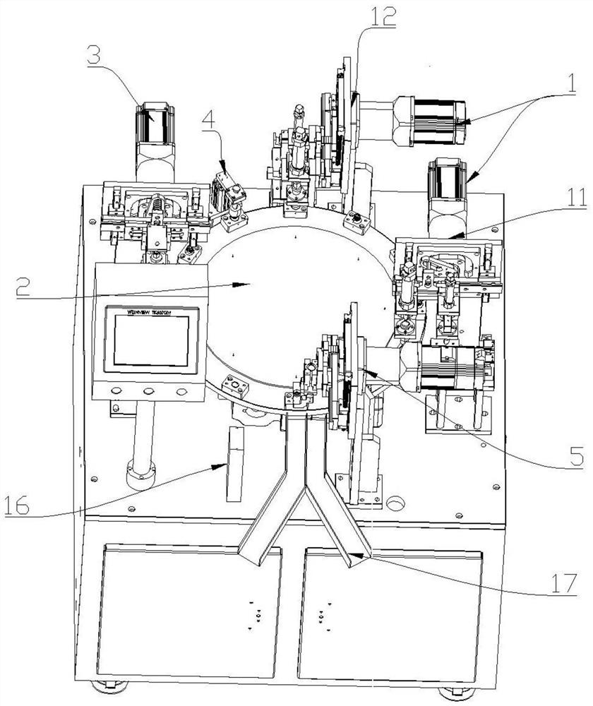
[0035] Such as figure 1 As shown, the fully automatic airtight connector O-ring assembly equipment includes a fully automatic O-ring assembly device 1, a turntable 2, an airtight connector feeding device 3, and a discharge device 5. According to the airtight connector The feeding device 3, the fully automatic O-ring assembly device 1 and the discharge device 5 are arranged around the turntable 2 in sequence; All are provided with moving mechanism 6.
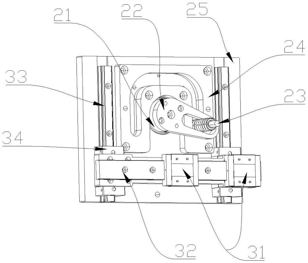
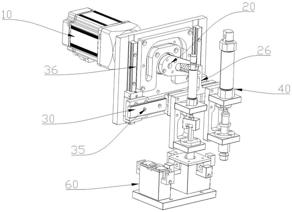
[0036] Such as figure 2 , 3 As shown, the moving mechanism 6 includes a drive mechanism 10, a cam mechanism 20 and a guide mechanism 30, and the cam mechanism 20 includes a turning block 21, a cam 22, a support rod 23 and a guide rail plate 24, and the turning block 21 and the driving mechanism 10 are connected with each other, and the cam 22 is fixedly connected to the rotary block 21. The protruding end of the cam 22 is provided with a strip-shaped groove, and a support rod 23 is vertically penetrated on the strip-shaped gr...
PUM
 Abstract
Description
Claims
Application Information
PatSnap Eureka turns technology decisions into work you can execute. Powered by our Innovation Knowledge Graph, it runs expert workflows across engineering, life sciences, materials and intellectual property. Get your review-ready output in minutes.


