Refrigerant transmission coupling device test system

A technology of coupling device and testing system, which is applied in the direction of measuring device, testing of mechanical parts, testing of fluid tightness, etc., can solve problems such as unsatisfactory, unusable, and unsuitable for the internal leakage rate test of refrigerant transmission coupling device, and achieve Improve work efficiency, save time, and facilitate assembly

Active Publication Date: 2022-03-11
VACREE TECH
View PDF12 Cites 0 Cited by
  • Summary
  • Abstract
  • Description
  • Claims
  • Application Information

AI Technical Summary

Problems solved by technology

However, due to the heat leakage of the cryogenic container itself and the conduction heat of the current lead, it is necessary to continuously replenish liquid nitrogen, and the working temperature of the magnet is around 77K, which cannot meet the requirements of the 30K temperature zone.
[0006] 2. Direct conduction cooling of superconducting magnets through cryogenic refrigerators. This method is simple and direct, but it cannot be applied to rotating superconducting motor rotating components 1-2, especially when the line speed is high
[0008] Publication No. CN104502843B discloses a patent for the invention of a superconducting low-temperature rotary test bench. The rotary test bench is designed for single-end rotation, and the state of superconducting materials and wrapping materials is tested when the superconducting motor is in the rotating state. Although it is also a test Superconducting motors at low temperature are not suitable for internal leakage rate test of refrigerant transmission coupling devices

Method used


Image

  • Refrigerant transmission coupling device test system
  • Refrigerant transmission coupling device test system
  • Refrigerant transmission coupling device test system

Examples


Embodiment 1

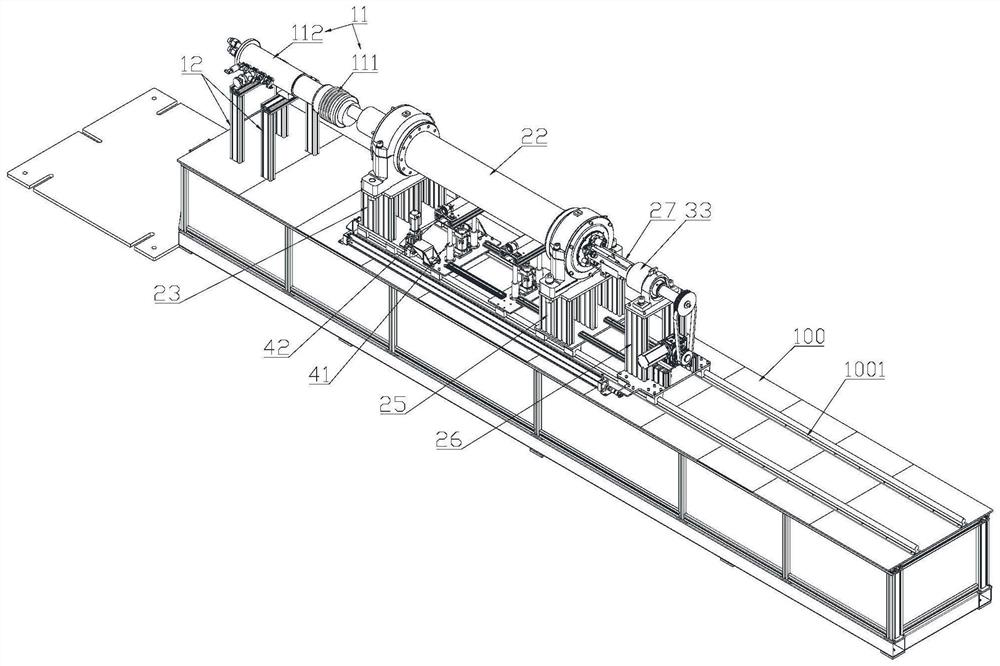
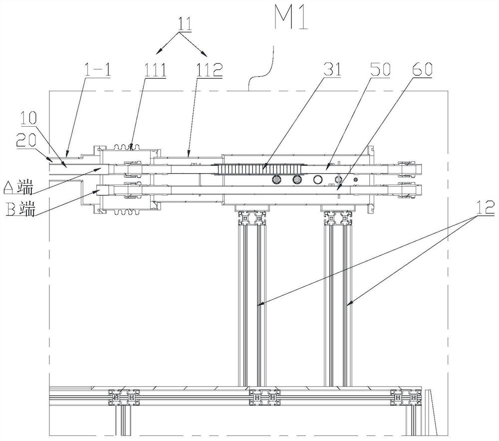
[0054] This embodiment discloses a test system for a refrigerant transmission coupling device, such as image 3 , Figure 4 As shown, the refrigerant transmission coupling device includes a stationary assembly 1-1 and a rotating assembly 1-2, the stationary assembly 1-1 is coaxially sleeved in the rotating assembly 1-2; the stationary assembly 1-1 is provided with a first refrigerant passage 10 and The second refrigerant passage 20, the first refrigerant passage 10 is an intake passage, the second refrigerant passage 20 is a return air passage, and the second refrigerant passage 20 is an annular passage sleeved outside the first refrigerant passage 10, and the first refrigerant passage 10 is an annular passage. 10 coaxial.

[0055] The test system includes a first vacuum chamber and a second vacuum chamber;

[0056] Such as figure 1 As shown, in this embodiment, the first vacuum chamber includes a first vacuum tube 11 and a third support 12; the first vacuum tube 11 include...

Embodiment 2

[0068] Such as Figure 5 As shown, in this embodiment, on the basis of implementing 1, in the second vacuum tube 22, two stabilizing rods 29 are also fixed, and the two straight pipes 402 are respectively fixed by the stabilizing frame and the stabilizing rod 29 at the corresponding position, further improving The stability of the straight pipe 402 is improved, and the vibration is reduced.

Embodiment 3

[0070] On the basis of Embodiment 1 and Embodiment 2, in this embodiment, a rail 1001 is provided on the workbench 100; the first bracket 23, the second bracket 25, and the fourth bracket 36 are slidably fixed on the rail 1001.

[0071] After disassembling the bellows, remove the internal pipeline joints, slide the first bracket 23, the second bracket 25, and the fourth bracket 36, and then the stationary component can be pulled out from the rotating component, so that the test system can be rotated without disassembly The overall movement of the end realizes the fast and convenient sample change of the sample to be tested;

[0072] Simultaneously, the second vacuum tube 22 is released from the fixed relationship with the first bracket 23, and the second bracket 25 and the fourth bracket 36 are slid to drive the second vacuum tube 22 and all parts fixed with the second bracket 25 and the fourth bracket 36. Move, so that the pipelines in the second vacuum chamber are exposed, a...


PUM


Abstract

The invention discloses a test system of a refrigerant transmission coupling device. Through the design of the bellows assembly and the sliding track, the refrigerant connection pipeline can be quickly disassembled, and the static assembly can be quickly replaced without greatly dismantling the equipment, realizing different The rapid replacement of the samples to be tested not only ensures the assembly accuracy of the equipment, but also saves time and improves work efficiency. The long-stem cryogenic valve is used as the turning point of the return air passage, which can not only demonstrate different openings according to the requirements, simulate the flow resistance load of different rotors, but also rotate with the system to realize the simulation of different speeds, satisfying the coupling of refrigerant transmission for different models to be tested. Device testing requirements. The test system provided by the present invention is used to test the efficiency of the refrigerant transmission coupling device, which is proposed for the first time in the technical field of refrigerant transmission coupling device testing.

Description

technical field [0001] The invention relates to the technical field of experimental equipment for a refrigerant transmission coupling device, in particular to a test system for a refrigerant transmission coupling device. Background technique [0002] Since the discovery of high-temperature superconducting materials in 1986, high-temperature superconducting materials have developed rapidly and have attracted the follow-up development of many countries in the world. The development and application fields of superconducting wires are becoming more and more extensive, such as superconducting current limiters and superconducting cables. , superconducting motors, superconducting magnetic energy storage, etc. [0003] Among them, superconducting motors have many advantages compared with ordinary motors, and are one of the future development directions of motors. At present, most superconducting motors are in the research and development stage. Due to the particularity of supercond...

Claims


Application Information

Patent Timeline
Patent Type & Authority Patents(China)
IPC IPC(8): G01N25/20G01M3/00G01M13/00
CPCG01N25/20G01M3/00G01M13/00
Inventor 董相文李阳苏玉磊何智张茜杜婉榕韩远昭章学华丁怀况
Owner VACREE TECH
Why Eureka
Try Eureka