
Backlight module and display module

A backlight module and backplane technology, applied in optics, nonlinear optics, instruments, etc., can solve problems such as large frame width, achieve ultra-thin cost, improve backlight effect, and low cost.

Pending Publication Date: 2021-11-30
BOE TECH GRP CO LTD +1
View PDF17 Cites 3 Cited by
  • Summary
  • Abstract
  • Description
  • Claims
  • Application Information

AI Technical Summary

Problems solved by technology

[0003] The present invention aims at the problem that the frame width of the backlight module of the above-mentioned COG+ backlight is larger, and provides a backlight module and a display module

Method used


Image

  • Backlight module and display module
  • Backlight module and display module
  • Backlight module and display module

Examples


Embodiment Construction

[0071] In order to enable those skilled in the art to better understand the technical solutions of the present invention, a backlight module and a display module of the present invention will be further described in detail below in conjunction with the accompanying drawings and specific embodiments.

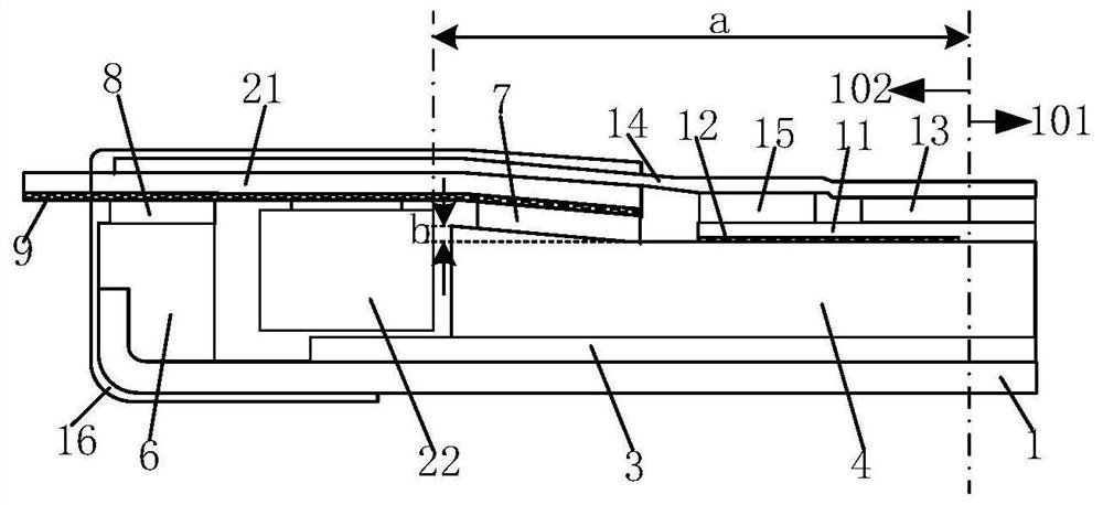
[0072] Currently, refer to Figure 3-Figure 5 , the COG+ backlight module is equipped with the premise that the width of the frame area 102 of the backlight module is narrowed to less than 3.0mm, and the backlight module needs to be ultra-thin. The backlight includes lamp beads 22 and circuit substrates 21 electrically connected to the lamp beads 22; The light-emitting surface of the backlight module lamp bead 22 in the backlight is facing the edge end surface of the light guide plate 4 (i.e., the light incident surface). The smooth side adopts a wedge-shaped flare design, and the other areas of the light guide plate 4 adopt a flat design. The wedge-shaped bell mouth design will...


PUM

PropertyMeasurementUnit
depthaaaaaaaaaa
depthaaaaaaaaaa

Abstract

The invention provides a backlight module which is provided with a middle area and a frame area. The backlight module comprises a back plate, a light bar in the frame area and comprising a circuit substrate and a lamp bead electrically connected, a reflective sheet arranged on the back plate, and a light guide plate arranged on one side of the reflective sheet away from the back plate. The reflective sheet and the light guide plate extend from the middle area to the frame area; the circuit substrate is positioned on one side of the light guide plate deviating from the reflective sheet; the light guide plate is uniform in thickness; the light-emitting surface of the lamp bead is opposite to the edge end surface of the light guide plate; the part, corresponding to the frame area, of the back plate is recessed in the direction away from the reflective sheet to form a first groove. And the orthographic projection of the reflective sheet on the back plate is not overlapped with the orthographic projection of the lamp bead on the back plate. According to the backlight module, the ultra-narrow frame can be achieved, the ultra-thin and low-cost effects can be achieved, meanwhile, the problems of hotspot and bright bands on the light-emitting face sides of the lamp beads can be solved, and the backlight effect of the backlight module is improved.

Description

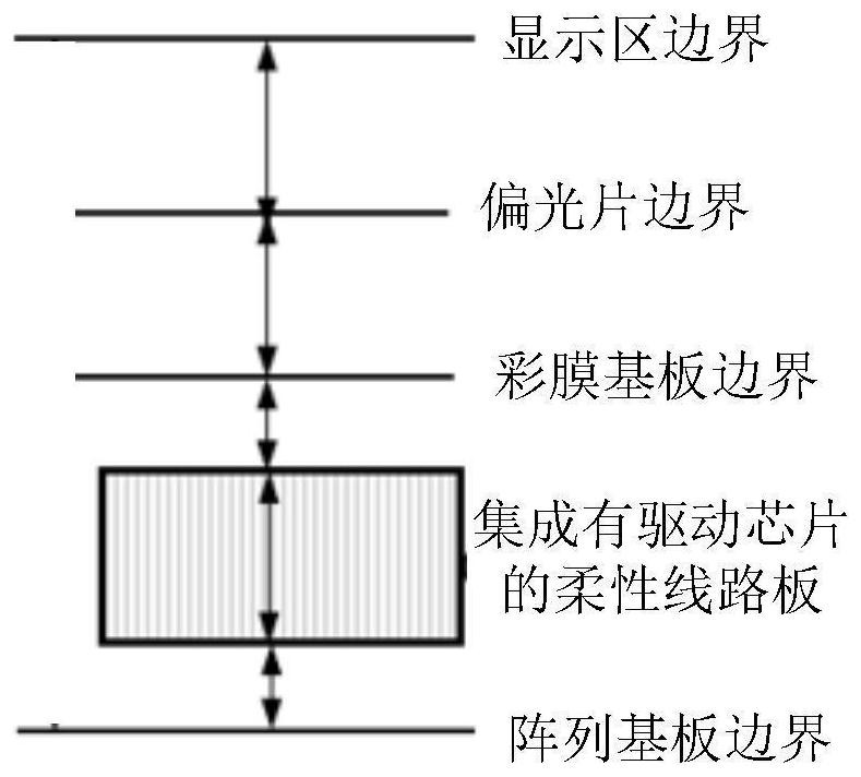
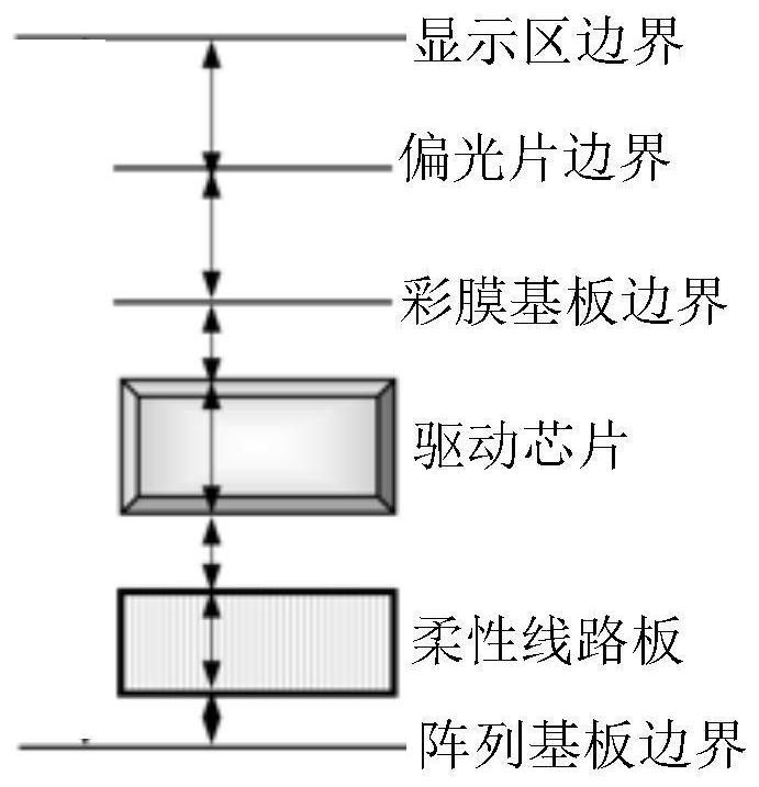
technical field [0001] The invention belongs to the field of display technology, and in particular relates to a backlight module and a display module. Background technique [0002] refer to figure 1 and figure 2 , due to the lack of COF (that is, the driver chip is integrated on the flexible circuit board), most of the backlight modules of display products currently use COG (that is, the driver chip is not integrated on the flexible circuit board, and the driver chip is directly set in the frame area of ​​​​the backlight module) + Backlight formal installation mode, COG+ backlight formal installation backlight module cost is much cheaper than COF+ backlight flip backlight module, but the disadvantage of COG+ backlight formal installation backlight module is that the frame width is relatively large, and mass production is currently available The bezel width is 3.2mm, which cannot meet the narrow bezel demand in the current market. The bezel width expected by the current ma...

Claims


Application Information

Patent Timeline
Patent Type & Authority Applications(China)
IPC IPC(8): G02F1/13357
CPCG02F1/1336G02F1/133612G02F1/133606G02F1/133605
Inventor 王耀东郑仰利张晓萍张罗刘芳怡印思琪高晓娟周震国任健
Owner BOE TECH GRP CO LTD
Learn More