
BJT device structure and manufacturing method thereof

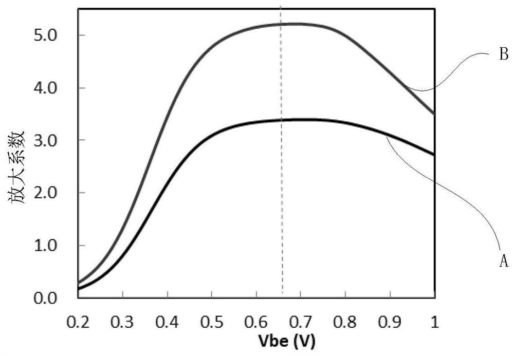
A technology of device structure and manufacturing method, which is applied in semiconductor/solid-state device manufacturing, semiconductor devices, electrical components, etc., can solve the problem of low amplification factor of BJT devices, and achieve the effect of reducing compound current and improving amplification factor.

Pending Publication Date: 2021-11-30
SHANGHAI HUALI INTEGRATED CIRCUIT CORP
View PDF0 Cites 0 Cited by
  • Summary
  • Abstract
  • Description
  • Claims
  • Application Information

AI Technical Summary

Problems solved by technology

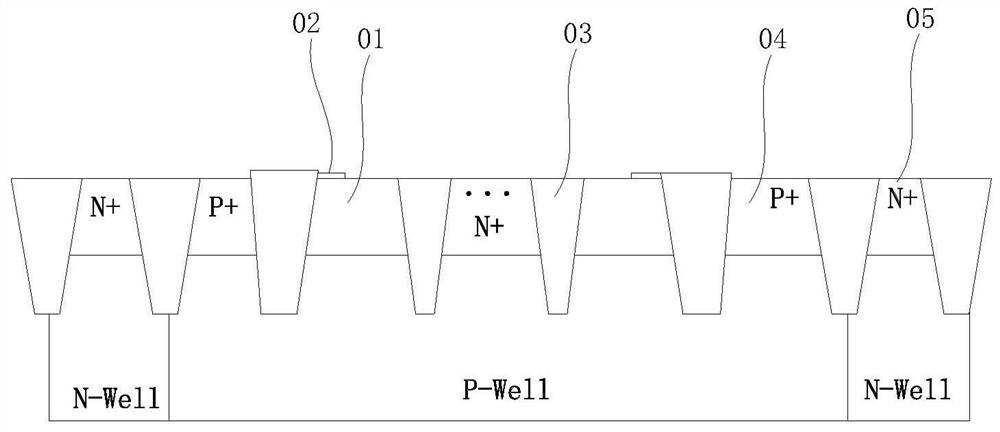
[0004] In view of the above-mentioned shortcomings of the prior art, the object of the present invention is to provide a BJT device structure and its manufacturing method, which is used to solve the problem of low amplification factor of the BJT device in the prior art

Method used


Image

  • BJT device structure and manufacturing method thereof
  • BJT device structure and manufacturing method thereof
  • BJT device structure and manufacturing method thereof

Examples


Embodiment Construction

[0029] Embodiments of the present invention are described below through specific examples, and those skilled in the art can easily understand other advantages and effects of the present invention from the content disclosed in this specification. The present invention can also be implemented or applied through other different specific implementation modes, and various modifications or changes can be made to the details in this specification based on different viewpoints and applications without departing from the spirit of the present invention.

[0030] see Figure 1 to Figure 5b . It should be noted that the diagrams provided in this embodiment are only schematically illustrating the basic idea of ​​the present invention, and only the components related to the present invention are shown in the diagrams rather than the number, shape and shape of the components in actual implementation. Dimensional drawing, the type, quantity and proportion of each component can be changed ar...


PUM

PropertyMeasurementUnit
sizeaaaaaaaaaa

Abstract

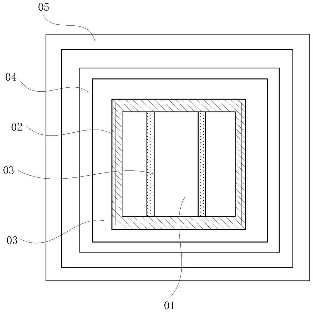
The invention provides a BJT device structure and a manufacturing method thereof. The structure comprises a P well; an N+ region which is positioned on the P well; a barrier layer structure which is located on the N+ region and is a frame-shaped structure surrounding the periphery of the N+ region, wherein the region in the barrier layer structure is an emitter region of the BJT device, the N+ region of the emitter region is provided with a plurality of STI regions which are arranged at intervals, and the upper surface of the P well is higher than the bottoms of the STI regions; a base region which is positioned on the periphery of the emitter region; and a collector region which is positioned on the periphery of the base region. The BJT device structure and the manufacturing method thereof have the following beneficial effects: the BJT device structure can significantly reduce the recombination current of the emitter region and the base region due to the fact that the STI region of the emitter region is a discontinuous structure. Therefore, the amplification coefficient of the BJT device is effectively improved.

Description

technical field [0001] The invention relates to the field of semiconductor manufacturing, in particular to a BJT device structure and a manufacturing method thereof. Background technique [0002] The bipolar junction transistor (BJT) in general logic circuits is parasitic based on the existing ion implantation conditions and cannot be adjusted independently, so it shows a relatively small beta (amplification factor), such as a BJT device with an NPN structure. Especially as the emitter area increases (other conditions remain unchanged), the current gain decreases significantly. Taking PNP as an example, its emitter is in the middle of the entire transistor, and the edge is surrounded by a barrier block (silicide block) to reduce recombination at the junction of the diffusion region and the STI region, thereby improving the performance of the BJT. At present, the typical production process of CMOS in the integrated process is as follows: (1) shallow trench isolation process ...

Claims


Application Information

Patent Timeline
Patent Type & Authority Applications(China)
IPC IPC(8): H01L29/735H01L29/06H01L21/331
CPCH01L29/735H01L29/0649H01L29/0684H01L29/6625H01L29/732H01L29/0813H01L29/0692
Inventor 王海涛周晓君
Owner SHANGHAI HUALI INTEGRATED CIRCUIT CORP
Learn More