Measuring tool for measuring turnout tie nail pitch of turnout in use state

A nail hole and measuring tool technology, applied in the field of measurement, can solve the problems of large errors, difficult direct measurement, and difficulty in determining the center of two nail holes, etc., to speed up the measurement speed, reduce the overall length, and reduce the effect of measurement error

Pending Publication Date: 2021-12-03
浙江贝尔轨道装备有限公司
View PDF0 Cites 0 Cited by
  • Summary
  • Abstract
  • Description
  • Claims
  • Application Information

AI Technical Summary

Problems solved by technology

[0003] In the current on-site operation, a tape measure is usually used to measure the distance between the nail holes of the turnout sleeper, which not only has a very large error, but also encounters many difficulties
For example, there will be rails between the nail holes and it is difficult to measure directly; because of the installed bolts of the turnout, it is difficult to determine the center of the two nail holes, etc.
In addition, in order to measure more accurate data as much as possible, the measurer also needs to cooperate with the skylight point of the railway operation, which brings greater work pressure to the on-site safety personnel
The accumulation of various on-site measurement errors will also have a huge impact on the design and transformation of turnouts

Method used


Image

  • Measuring tool for measuring turnout tie nail pitch of turnout in use state
  • Measuring tool for measuring turnout tie nail pitch of turnout in use state
  • Measuring tool for measuring turnout tie nail pitch of turnout in use state

Examples


Embodiment Construction

[0028] The specific implementation manners of the present invention will be described in detail below in conjunction with the accompanying drawings.

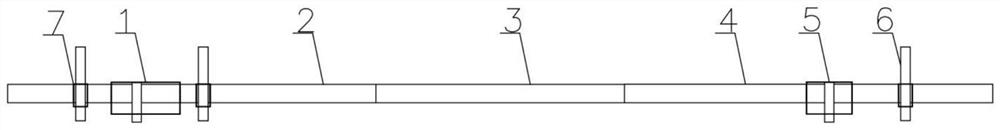
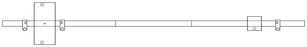
[0029] Such as figure 1 , 2 As shown in , 6, the measuring tool for measuring the distance between the nail holes of the turnout for the turnout in use includes: two rail positioning parts, a group of telescopic rods, three nail hole positioning parts 7 and four nail hole auxiliary positioning parts 8 .

[0030] The rail locating member includes a first rail locating member 1 and a second rail locating member 5, which have a through hole extending horizontally, and a downwardly protruding positioning post is provided on its bottom surface;

[0031] The surface of the telescopic rod has a size scale for marking the distance, and one end of it passes through the through hole of the first rail locator 1 and is locked by a stopper; the other end of the telescopic rod passes through the through hole of the second rail locator 5 , ...


PUM


Abstract

The invention relates to a measuring technology, and aims to provide a measuring tool for measuring a turnout tie nail pitch of a turnout in a use state. The measuring tool comprises two rail positioning pieces which are provided with horizontally-penetrating through holes, and positioning columns protruding downwards are arranged on the bottom faces of the rail positioning pieces; a telescopic rod with scales on the surface penetrates the two rail positioning pieces, one of the rail positioning pieces is locked by a limiting device, the other one can freely move on the telescopic rod; and three nail hole positioning pieces are movably arranged on the telescopic rod in a sleeving manner and are used for realizing vertically downward positioning indication. The measuring tool can be directly erected on the steel rail at the position where the nail hole distance needs to be measured, and the relative distance between the nail holes and the relative distance between the nail holes and the non-working edge of the steel rail can be conveniently and rapidly determined. Manual visual inspection, tape pulling and other operations in a traditional measurement mode are not needed, and the measurement speed can be greatly increased. The measuring tool is suitable for various measuring environments, and compared with a traditional measurement mode, the measurement error is greatly reduced. The measuring tool can be detached and contracted, has a reduced overall length and is more convenient to carry compared with a traditional measuring tool.

Description

technical field [0001] The invention relates to measurement technology, in particular to a measuring tool for measuring the distance between nail holes in a turnout for a turnout in use. Background technique [0002] The fixing method of the turnout product is usually: use two bolts to fix an iron backing plate with a set of fixing components on the switch sleeper, put the rail between the fixing components, and use the bolts and elastic clips to clamp the bottom of both sides of the rail. hold fixed. When designing and modifying the laid turnout products, because the installation conditions of each turnout sleeper are different, the precise size of the on-site products is required, including the nail hole distance of the turnout tie. However, if there was no work arrangement for replacing and disassembling the switch sleeper, it would not be possible to directly measure the distance between the nail holes of the switch sleeper. At this time, technical drawings or data rel...

Claims


Application Information

Patent Timeline
Patent Type & Authority Applications(China)
IPC IPC(8): E01B35/02
CPCE01B35/02E01B2203/16
Inventor 刘阳赵巍孙莹李艳倪林华李文萍徐剑林王中华胡俊安
Owner 浙江贝尔轨道装备有限公司
Why Eureka
Try Eureka