Assembling platform positioning mechanism of full-automatic backlight assembling machine

A positioning mechanism and assembly machine technology, applied in the direction of workpiece clamping devices, manufacturing tools, hand-held tools, etc., can solve the problems of inability to position panels of different models, affect the efficiency and quality of backlight installation, and achieve the convenience of backlight installation, Avoid shaking effects

Pending Publication Date: 2021-12-07
湖北顺通光电科技有限公司
View PDF1 Cites 1 Cited by
  • Summary
  • Abstract
  • Description
  • Claims
  • Application Information

AI Technical Summary

Problems solved by technology

[0005] The purpose of the present invention is to solve the shortcomings in the prior art that the panels of different models cannot be positioned, thereby affecting the subsequent backlight installation efficiency and installation quality, and propose a fully automatic backlight assembly machine assembly platform positioning mechanism

Method used


Image

  • Assembling platform positioning mechanism of full-automatic backlight assembling machine
  • Assembling platform positioning mechanism of full-automatic backlight assembling machine
  • Assembling platform positioning mechanism of full-automatic backlight assembling machine

Examples


Embodiment 1

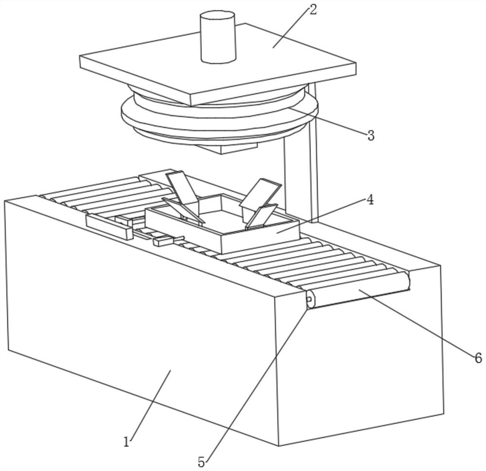
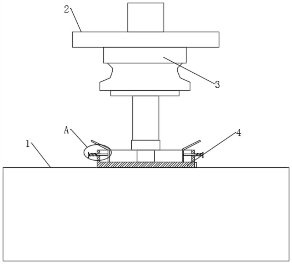
[0032] like Figure 1-4 As shown, a fully automatic backlight assembly machine assembly platform positioning mechanism electric bicycle motor detection device proposed by the present invention includes a base 1 and a backlight installation mechanism 3, the outside of the base 1 is provided with a moving groove 5, and the inside of the moving groove 5 A plurality of moving rollers 6 are rotatably connected, and the outside of the moving rollers 6 is provided with an installation platform 4, and the inside of the installation platform 4 is slidably connected with a limit unit for installing the screen. The mounting mechanism 3 is installed on the outside of the mounting plate 2, and the mounting platform 4 is slidingly connected to the outside of the moving roller 6;

[0033] The limit unit includes a plurality of positioning grooves 7 opened on the outside of the installation platform 4, the inside of the positioning grooves 7 is slidably connected with a connecting rod 8, and ...

Embodiment 2

[0037] like figure 1 , figure 2 , image 3 and Figure 5As shown, based on the first embodiment, the outside of the base 1 is provided with a clamping unit for fixing the installation platform 4. The clamping unit includes two fixing blocks 12 installed on the outside of the base 1. The fixing blocks 12 There is a shrinking groove 13 inside the shrinking groove 13, and a clamping block 15 is slidably connected to the inside of the shrinking groove 13, and the two fixing blocks 12 are arranged symmetrically. The outside of the installation platform 4 is symmetrically provided with a clamping groove 16, and the clamping block 15 is far away from the shrinkage One end inside the groove 13 is pressed against the inside of the clamping groove 16, and a spring b14 is installed inside the shrinking groove 13, and the end of the spring b14 away from the shrinking groove 13 is connected to the outside of the clamping block 15, and the cross section of the clamping block 15 It is se...

Embodiment 3

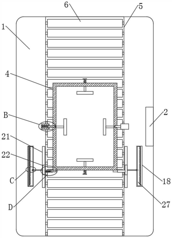
[0040] like Figure 1-7 As shown, based on the above-mentioned embodiment one or two, the outside of the base 1 is also provided with an observation unit for checking the moving distance of the installation platform 4. The observation unit includes two observation boxes 18 installed on the outside of the base 1, and the observation box The outside of 18 is provided with locking groove 17, and the exterior of base 1 is provided with chute 21 symmetrically, and the inside of chute 21 is slidably connected with sliding block 22, and the side of sliding block 22 near installation platform 4 is equipped with transmission block 23, two Two observation boxes 18 are symmetrically arranged;

[0041] The inside of the transmission block 23 is provided with a transmission groove 24, the inside of the transmission groove 24 is slidingly connected with a transmission rod 25, the inside of the transmission groove 24 is equipped with a spring c26, and the end of the spring c26 away from the ...


PUM


Abstract

The invention discloses an assembling platform positioning mechanism of a full-automatic backlight assembling machine, and relates to the field of backlight assembly. The technical scheme adopted by the invention is that the assembling platform positioning mechanism comprises a base and a backlight mounting mechanism, a moving groove is formed in the outer portion of the base, a plurality of moving rollers are rotationally connected into the moving groove, a mounting platform is arranged outside the moving rollers, a limiting unit used for mounting a workpiece is slidably connected into the mounting platform, and a clamping unit used for fixing the mounting platform is arranged outside the base. Preliminary positioning of the workpiece can be achieved through cooperative use of extrusion plates and guide plates in the limiting unit, the guide plates are obliquely arranged relative to the base, and therefore a panel can be conveniently placed. After the workpiece is placed in the mounting platform, due to the fact that the extrusion plates are symmetrically arranged, the workpiece can be located in the center of the mounting platform under the elastic force of a spring a, and then the workpieces of various models can be preliminarily located.

Description

technical field [0001] The invention relates to the technical field of backlight assembly, in particular to a positioning mechanism for an assembly platform of a fully automatic backlight assembly machine. Background technique [0002] The main function of the backlight is to provide a uniform background light source. The backlight automatic assembly machine is to automatically assemble the small backlight module on the fixture tray according to the production process requirements, so as to generate a qualified display device. [0003] After searching, the invention patent with the Chinese patent number CN108382863A discloses a fully automatic backlight assembly machine, including a body, a control switch is arranged on the front surface of the body, and a stand, and a frame is installed on the upper surface of the body near the front of the stand, a first induction mechanism is installed on the upper surface of the body near the side of the frame, and the upper surface of t...

Claims


Application Information

Patent Timeline
Patent Type & Authority Applications(China)
IPC IPC(8): B25B11/02B25B27/00
CPCB25B11/02B25B27/00
Inventor 郑凤军吕俊开易文娟祝伟钊
Owner 湖北顺通光电科技有限公司
Why Eureka
Try Eureka