Swing gate with anti-collision function

A functional and anti-collision technology, applied in the field of channel management, can solve the problems of increasing the operating cost of the swing gate, damage to the motor, shortening the service life of the swing gate, etc., and achieve the effect of smooth and stable movement, prolonging the service life and reducing operating costs

Active Publication Date: 2021-12-07
北京中成科信科技发展有限公司
View PDF10 Cites 3 Cited by
  • Summary
  • Abstract
  • Description
  • Claims
  • Application Information

AI Technical Summary

Problems solved by technology

[0002] Swing gates are usually used for pedestrian passage management and can be widely used in airports, stations, scenic spots and other places. The blocking body is generally a swing gate, which is perpendicular to the ground, and the function of blocking and releasing is realized by rotating the swing gate; the existing swing gate Usually it is rigidly connected and fixed with the motor. When the swing gate is closed and a pedestrian bumps into the swing gate, the impact force on the swing gate will directly act on the motor, resulting in damage to the motor, which will shorten the service life of the swing gate and increase the swing gate. Gate operating costs

Method used


Image

  • Swing gate with anti-collision function
  • Swing gate with anti-collision function
  • Swing gate with anti-collision function

Examples


Embodiment Construction

[0044] The present invention will be further described in detail below in conjunction with the accompanying drawings, so that those skilled in the art can implement it with reference to the description.

[0045] It should be noted that in the description of the present invention, the indicated orientation or positional relationship is based on the orientation or positional relationship shown in the drawings, which is only for the convenience of describing the present invention and simplifying the description, and does not indicate or imply the indicated device Or elements must have a certain orientation, be constructed and operate in a certain orientation, and thus should not be construed as limiting the invention.

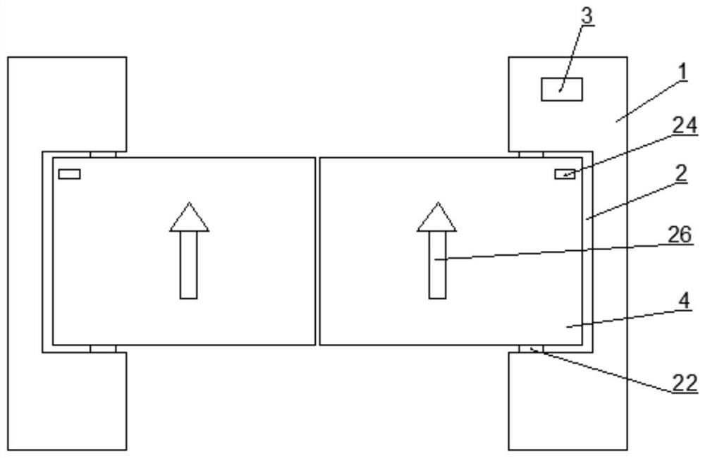
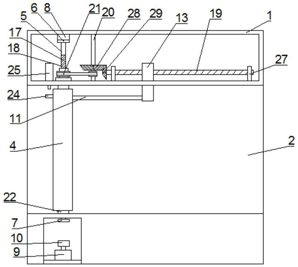
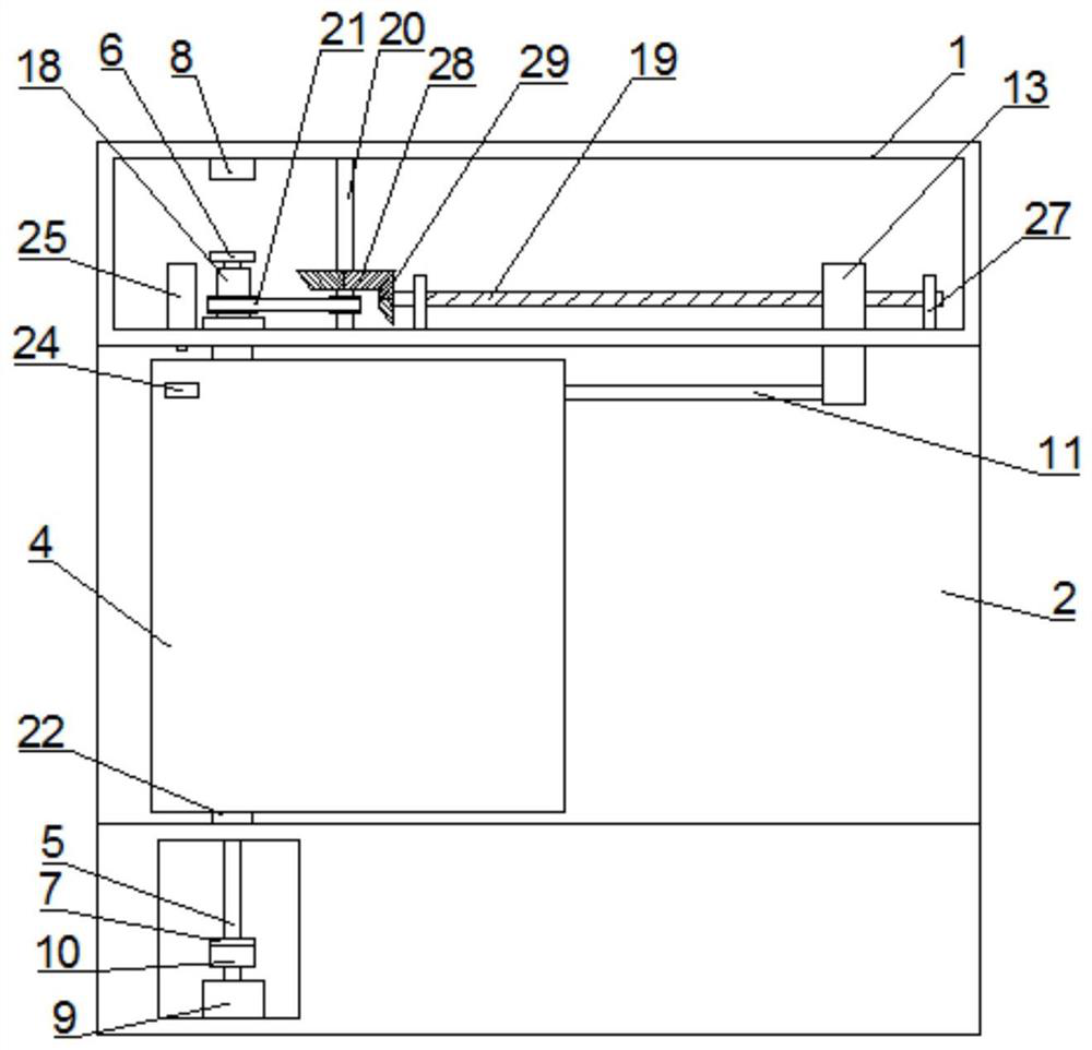
[0046] Such as Figure 1-9 As shown, the present invention provides a swing gate with anti-collision function, including:

[0047] Cabinet 1, it is provided with groove 2 near the middle part of a side of channel, and the side of described cabinet 1 near channel ...


PUM


Abstract

The invention discloses a swing gate with an anti-collision function. The swing gate comprises a case which is provided with a groove on one side surface, a swing gate vertically and rotatably arranged in the groove, a vertical rod vertically arranged in the swing gate and slidably connected with the swing gate in the vertical direction, a first electromagnet, a servo motor, a supporting rod and a control unit, wherein the upper end and the lower end of the vertical rod are located in the case, and a first electromagnet attraction piece and a second electromagnet attraction piece are fixedly arranged at the upper end and the lower end of the vertical rod correspondingly; the first electromagnet is arranged right above the first electromagnet attraction piece; an output shaft of the servo motor is vertically arranged, and the servo motor is fixedly provided with a second electromagnet located under the second electromagnet attraction piece; the supporting rod is horizontally arranged on the back surface of the swing gate, one end of the supporting rod is slidably connected with the swing gate through a first sliding block, and the other end of the supporting rod is slidably connected with the case through a second sliding block; and the two ends of the supporting rod are hinged to the first sliding block and the second sliding block correspondingly. Damage to the motor can be effectively reduced, and the beneficial effects of prolonging the service life and reducing the operation cost are achieved.

Description

technical field [0001] The invention relates to the technical field of channel management. More specifically, the present invention relates to a swing gate with anti-collision function. Background technique [0002] Swing gates are usually used for pedestrian passage management and can be widely used in airports, stations, scenic spots and other places. The blocking body is generally a swing gate, which is perpendicular to the ground, and the function of blocking and releasing is realized by rotating the swing gate; the existing swing gate Usually it is rigidly connected and fixed with the motor. When the swing gate is closed and a pedestrian bumps into the swing gate, the impact force on the swing gate will directly act on the motor, resulting in damage to the motor, which will shorten the service life of the swing gate and increase the swing gate. Gate operating costs. Contents of the invention [0003] It is an object of the present invention to solve at least the abo...

Claims


Application Information

Patent Timeline
Patent Type & Authority Applications(China)
IPC IPC(8): E01F13/06E01F9/669
CPCE01F13/06E01F9/669
Inventor 焦岩魏建刚陈齐军
Owner 北京中成科信科技发展有限公司
Why Eureka
Try Eureka