
Working method of bridge water drainage device

A drainage device and working method technology, applied in bridges, bridge parts, bridge construction, etc., can solve the problems of wheel slippage, high cost, low utilization rate, etc., and achieve the effect of avoiding blockage and simple structure

Active Publication Date: 2019-02-15
佛山市市政建设工程有限公司
View PDF8 Cites 0 Cited by
  • Summary
  • Abstract
  • Description
  • Claims
  • Application Information

AI Technical Summary

Problems solved by technology

[0002] If there is too much water on the bridge, it will easily reduce the friction between the tires and the bridge deck, which will cause the wheels to slip and easily lead to traffic accidents. Therefore, the role of the bridge drainage system is particularly important, but the bridge deck is full of gravel, and There are other garbage, which can easily cause pipe blockage under the rainwater alluvial
[0003] Chinese Patent No. CN105862585B has announced a bridge deck sewage treatment device, including a water collection channel, which is characterized in that the water collection channel is connected to a separation box, and a water filter plate is arranged in the separation box, and the bottom of the water filter plate is arranged There is a water collecting tank, and the spoke rotor driven by the motor is installed above the water filter plate; the discharge port of the spoke rotor is equipped with a conveyor belt driven by a conveyor belt motor, and the discharge end of the conveyor belt is installed with a garbage outlet stop; A cold air blowing pipe is connected above the conveyor belt in the separation box; this patent is mainly used to purify sewage, but the bridge deck area is not large, and multiple sewage treatment devices should be installed along the length of the bridge body, which makes each sewage treatment device treat The amount of sewage is small, and the rainy and snowy weather is not fixed, and the sewage treatment device is used less frequently. However, the invention has a complex structure and more equipment, which makes its cost higher and corresponds to a lower utilization rate, which is serious. It leads to economic waste, and secondly, the follow-up treatment of solid impurities in the device is inconvenient
This patent has similar problems with the above-mentioned patents. The complex structure and many equipments lead to high cost, and the maintenance is inconvenient. Its cost cannot match its utilization rate.

Method used


Image

  • Working method of bridge water drainage device
  • Working method of bridge water drainage device
  • Working method of bridge water drainage device

Examples


Embodiment Construction

[0036]The following will be combined with Figure 1 to Figure 11 The present invention is described in detail, and the technical solutions in the embodiments of the present invention are clearly and completely described. Apparently, the described embodiments are only some of the embodiments of the present invention, not all of them. Based on the embodiments of the present invention, all other embodiments obtained by persons of ordinary skill in the art without making creative efforts belong to the protection scope of the present invention.

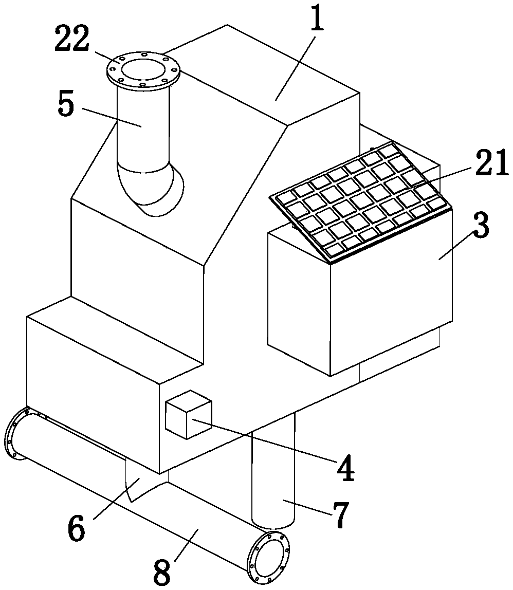
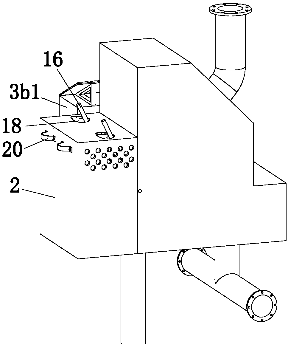
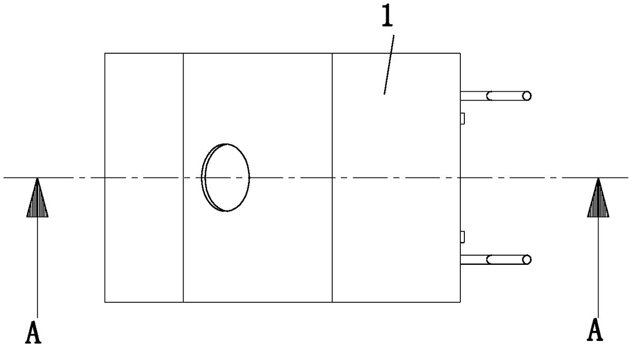
[0037] The present invention provides a bridge drainage device through improvement, such as Figure 1-Figure 11 As shown, it includes a treatment box 1, a dirt collection box 2, a filter mechanism 3 and an oil removal mechanism 4. The treatment box 1 is provided with a filter cavity 1a, an oil suction cavity 1b and an oil collection cavity 1c, and the filter mechanism 3 and the oil removal mechanism The oil mechanism 4 is respectively ins...


PUM


Abstract

The invention relates to the field of bridge equipment, specifically to a bridge water drainage device. The bridge water drainage device comprises a treatment box, a dirt collecting box, a filtering mechanism and an oil removing mechanism; a filtering cavity, an oil suction cavity and an oil collecting cavity are formed in the treatment box; the filtering mechanism and the oil removing mechanism are correspondingly mounted in the filtering cavity and the oil suction cavity; the dirt collecting box is positioned on one side of the treatment box; a water inlet pipe is arranged at the upper end of the treatment box; an oil drain pipe and a water drainage pipe are arranged at the lower end of the treatment box; an oil collecting pipe communicating with the oil drain pipe is arranged at the lower end of the oil drain pipe; a material outlet is formed in one side of the treatment box; a material stopping component is arranged in the material outlet; the filtering mechanism comprises a filtering net and a swinging component; a hinging shaft is arranged at one end of the filtering net; and the filtering net is hinged to the treatment box through the hinging shaft. The bridge water drainagedevice has the beneficial effects that greasy dirt and sand stones in drained water can be drained to prevent pipeline blockage; and moreover, the structure is simple, and the manufacturing cost is lower.

Description

technical field [0001] The invention relates to the field of bridge equipment, in particular to a working method of a bridge drainage device. Background technique [0002] If there is too much water on the bridge, it will easily reduce the friction between the tires and the bridge deck, which will cause the wheels to slip and easily lead to traffic accidents. Therefore, the role of the bridge drainage system is particularly important, but the bridge deck is full of gravel, and There are also other garbage, which can easily cause pipe blockage under the alluvial rainwater. [0003] Chinese Patent No. CN105862585B has announced a bridge deck sewage treatment device, including a water collection channel, which is characterized in that the water collection channel is connected to a separation box, and a water filter plate is arranged in the separation box, and the bottom of the water filter plate is arranged There is a water collecting tank, and the spoke rotor driven by the mo...

Claims


Application Information

Patent Timeline
Patent Type & Authority Applications(China)
IPC IPC(8): E01D19/08
CPCE01D19/086
Inventor 闫平洋初丽萍李启同
Owner 佛山市市政建设工程有限公司
Learn More