Quick dismounting type grabbing device

A grabbing device and detachable technology, which is applied in the field of quick-dismantling grabbing devices, can solve the problems of time-consuming disassembly and installation, blockage of the filter layer, and increased time for maintenance personnel to disassemble and install, so as to reduce the number and avoid reverse flow, avoid shaking effect

Active Publication Date: 2021-12-10
SUZHOU DITIAN ROBOT & AUTOMATION CO LTD
View PDF5 Cites 0 Cited by
  • Summary
  • Abstract
  • Description
  • Claims
  • Application Information

AI Technical Summary

Problems solved by technology

[0003] A filter layer is set between the high-fluidity particles of the grasping device and the trachea. After the high-fluidity particles are stuck in the filter layer, it is difficult for the inflator to blow out the high-fluidity particles stuck in the filter layer by inflating through the trachea, causing the filter layer to be blocked. The flange is connected by multiple bolts, which is time-consuming for disassembly and installation, which increases the time for maintenance personnel to disassemble and install

Method used


Image

  • Quick dismounting type grabbing device
  • Quick dismounting type grabbing device
  • Quick dismounting type grabbing device

Examples


Embodiment 1

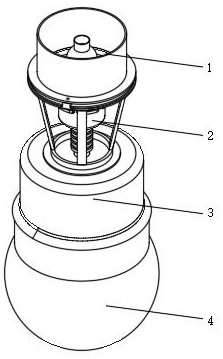
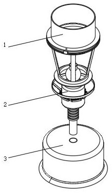
[0035] Such as figure 1 , 2 , 3, 4, 5, 6, 8, and 9, a quick-detachable grabbing device includes a connecting cover 3, a grabbing end 4 and a first inflation tube 5, and the lower end cavity connecting the cover 3 is provided There is a grasping end 4, and a first inflation tube 5 is inserted into the opening at the upper end of the connecting cover 3, and the first inflation tube 5 is connected to the grasping end 4;

[0036] The upper end of the connecting cover 3 is provided with a quick-release connecting flange 1, and the inside of the quick-release connecting flange 1 is provided with a shaking filter device 2;

[0037] The quick-release connecting flange 1 includes a first connecting ring 103, an L-shaped insert 104, a second connecting ring 105, a third connecting ring 106 and a ring groove 107, and the upper end of the first connecting ring 103 is provided with two L-shaped inserts. Block 104, the upper end of the first connecting ring 103 is provided with a second c...

Embodiment 2

[0040] Such as Figure 5 , 6As shown, the components that are the same as or corresponding to those in the first embodiment are marked with the corresponding reference numerals in the first embodiment. For the sake of simplicity, only the differences from the first embodiment will be described below. The difference is that the quick-release connecting flange 1 also includes a bottom ring 101, a support bar 102 and a fixing cylinder 108, the lower end of the first connecting ring 103 is provided with a support bar 102, and the lower end of the support bar 102 is provided with a bottom ring 101 , the upper end of the third connecting ring 106 is provided with a fixed cylinder 108;

[0041] The bottom ring 101, the support bar 102 and the first connecting ring 103 are set in the shape of a cone, the minimum distance between two adjacent support bars 102 is the same as the diameter of the transparent filter cartridge 203, and one of the L-shaped inserts 104 runs through the secon...

Embodiment 3

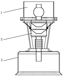
[0043] Such as Figure 6 , 7 , 9, wherein the same or corresponding components as those in the first embodiment use the corresponding reference numerals as in the first embodiment. For the sake of brevity, only the differences from the first embodiment will be described below. The difference is that the vibrating filter device 2 also includes a first connecting pipe 206, a connecting hose 207, a ring 208, a square bar 209, an arc cover 210, a spring 211, an arc bar 212 and a rubber pad 213, transparent A first connecting pipe 206 and a connecting hose 207 are provided between the filter cartridge 203 and the first inflation pipeline 5, the upper end of the first connecting pipe 206 is connected with the transparent filter cartridge 203, and the lower end of the first connecting pipe 206 is connected with a connecting hose 207, The inner ring of the first connection ring 103 is provided with a circular ring 208, and the lower end of the circular ring 208 is provided with six s...


PUM


Abstract

The invention discloses a quick dismounting type grabbing device, and belongs to the technical field of mechanical grabbing. The grabbing device comprises a connecting cover body, a grabbing end and a first inflation pipe, the grabbing end is arranged in a lower end cavity of the connecting cover body, the first inflation pipe is inserted into an upper end opening of the connecting cover body, the first inflation pipe is connected with the grabbing end, a quick dismounting type connecting flange is arranged at the upper end of the connecting cover body, and a shaking type filtering device is arranged in the quick dismounting type connecting flange. According to the quick dismounting type grabbing device, an L-shaped embedded block, three connecting rings and an annular groove are matched with one another, the L-shaped embedded block is embedded into the annular groove, bolts are adopted for connection, the number of the bolts is reduced, the mounting and dismounting speed is increased, the L-shaped embedded block is matched with the annular groove, clamping of the first connecting ring and the second connecting ring is achieved, shaking between the first connecting ring and the second connecting ring is avoided, and the connecting stability is improved; when a substance at the grabbing end is clamped at the filtering layer, an air bag is inflated in an intermittent inflation mode, so that shaking of the air bag is realized, and shaking of a transparent filter cartridge and the filtering layer is intensified.

Description

technical field [0001] The invention relates to the technical field of mechanical grabbing, in particular to a quick-detachable grabbing device. Background technique [0002] The Chinese utility model patent application number is CN202020140534.5, and the patent name is a grabbing device for grabbing objects. The grabbing device includes a connecting seat, one end connected to the connecting seat and a hollow cavity. The grasping end, the first air pipe provided in the connecting seat for communicating with the grasping end, the high-fluidity particles filled in the hollow cavity, and the first air pipe arranged between the hollow cavity and the first air pipe The filter layer used to prevent the high mobility particles from entering the first air pipe between them; [0003] A filter layer is set between the high-fluidity particles of the grasping device and the trachea. After the high-fluidity particles are stuck in the filter layer, it is difficult for the inflator to blo...

Claims


Application Information

Patent Timeline
Patent Type & Authority Applications(China)
IPC IPC(8): B25J15/00B25J15/08
CPCB25J15/0023B25J15/08
Inventor 万信飞赵德强支海波陆郭春黄仕茌
Owner SUZHOU DITIAN ROBOT & AUTOMATION CO LTD
Why Eureka
Try Eureka