Automobile speed change control mechanism

A control mechanism and automobile technology, applied in the direction of mechanical equipment, toothed components, belts/chains/gears, etc., can solve the problems of the driver mistakenly engaging the reverse gear, cumbersome operation, easy shaking, etc., and achieve the interlocking function , feel the obvious effect

Pending Publication Date: 2021-12-10
YANCHENG BUGAO AUTO PARTS MFG CO LTD
View PDF6 Cites 2 Cited by
  • Summary
  • Abstract
  • Description
  • Claims
  • Application Information

AI Technical Summary

Problems solved by technology

[0002] The transmission control mechanism is used to change the collocation of transmission gears to achieve gear shifting. Under the operation of the driver, the transmission control mechanism can quickly, accurately and reliably remove, engage in a certain gear or return to neutral. The existing The transmission control mechanism is easy to shake in the transmission, and the safety of the transmission cannot be guaranteed, and the driver is likely to mistakenly engage the reverse gear while driving, which increases the risk of driving, and does not allow the driver to determine the shift shaft when shifting gears. Whether the switch is in place, the operation is cumbersome, so it is necessary to improve the structure of the transmission control mechanism

Method used


Image

  • Automobile speed change control mechanism
  • Automobile speed change control mechanism
  • Automobile speed change control mechanism

Examples


Embodiment 1

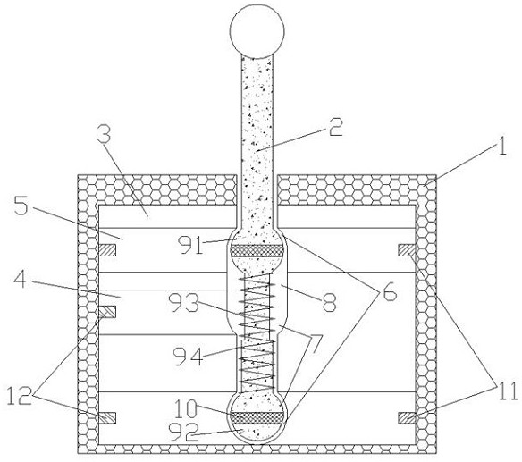
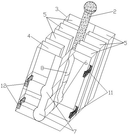
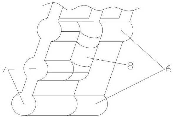
[0019] Embodiment 1: see Figure 1~Figure 4 , an automobile transmission control mechanism, comprising an operating base 1, a joystick 2, the inside of the operating base 1 is provided with a gear limit disc 3, and the gear limit disc 3 is provided with a reverse gear slot 4 and a plurality of forward gear slots 5 , the forward gear grooves 5 are symmetrically arranged and parallel to each other, the reverse gear grooves 4 are located on one side of the forward gear grooves 5 and are arranged in parallel with the forward gear grooves 5; the forward gear grooves 5 communicate with each other through the forward guide grooves 6 arranged horizontally, A reverse guide groove 7 arranged horizontally is arranged in the groove 4 .

[0020] The joystick 2 is inserted into the forward guide groove 6, and the bottom of the joystick 2 is provided with a guide block 9. The guide block 9 includes an upper guide block 91, a lower guide block 92, a telescopic rod 93 and a compression spring ...


PUM


Abstract

The invention relates to an automobile speed change control mechanism. The automobile speed change control mechanism comprises an operation base and a control rod, wherein a gear limiting disc is arranged inside the operation base; a reverse gear groove and a plurality of forward gear grooves are formed in the gear limiting disc, the forward gear grooves communicates with one another through a horizontally-arranged forward guide groove, and a horizontally-arranged reverse gear guide groove is formed in the reverse gear groove; the control rod is inserted into the forward guide groove, and a guide block is arranged at the bottom of the control rod and comprises an upper guide block, a lower guide block, a telescopic rod and a compression spring; and when the compression spring is in a balanced state, the forward guide groove is matched with the guide block in a balanced state, when the compression spring is in a compressed state, the reverse gear guide groove is matched with the guide block in a compressed state, and the reverse gear guide groove is connected with the forward guide groove through a limiting groove. When the control rod is engaged into a reverse gear, the control rod needs to be compressed downwards until the telescopic rod is shortest, the guide block moves into the reverse gear groove after entering the reverse gear guide groove, and the control rod is prevented from being engaged into the reverse gear groove due to misoperation when located in the forward guide groove.

Description

technical field [0001] The invention relates to the technical field of automobile transmissions, in particular to an automobile transmission control mechanism. Background technique [0002] The transmission control mechanism is used to change the collocation of transmission gears to achieve gear shifting. Under the operation of the driver, the transmission control mechanism can quickly, accurately and reliably remove, engage in a certain gear or return to neutral. The existing The transmission control mechanism is easy to shake in the transmission, and the safety of the transmission cannot be guaranteed, and the driver is likely to mistakenly engage the reverse gear while driving, which increases the risk of driving, and does not allow the driver to determine the shift shaft when shifting gears. It is cumbersome to operate whether the switch is in place, so it is necessary to improve the structure of the transmission control mechanism. Contents of the invention [0003] T...

Claims


Application Information

Patent Timeline
Patent Type & Authority Applications(China)
IPC IPC(8): F16H59/02
CPCF16H59/02F16H59/0278F16H2059/0291F16H2059/0269F16H2059/0282
Inventor 陈永红陈昕宇曹福顺张栋梁陈永青
Owner YANCHENG BUGAO AUTO PARTS MFG CO LTD
Why Eureka
Try Eureka