Supercharge Your Innovation With Domain-Expert AI Agents!

Method for eliminating defects in image and printer by using the method

A technology that changes the print head and method. It is used in the field of masking or reducing misalignment defects. It can solve the problems of lowering printing speed and shortening the drying time of media, so as to achieve the effect of high printing speed.

Inactive Publication Date: 2004-02-11
MARKEM IMAJE HLDG
View PDF3 Cites 0 Cited by
  • Summary
  • Abstract
  • Description
  • Claims
  • Application Information

AI Technical Summary

Problems solved by technology

An advantage of this solution, usually involving a high overlap rate, is the ability to reduce the drying time of the media, but slows down the print speed by a factor of 2 to 16

Method used


Image

  • Method for eliminating defects in image and printer by using the method
  • Method for eliminating defects in image and printer by using the method
  • Method for eliminating defects in image and printer by using the method

Examples


Embodiment Construction

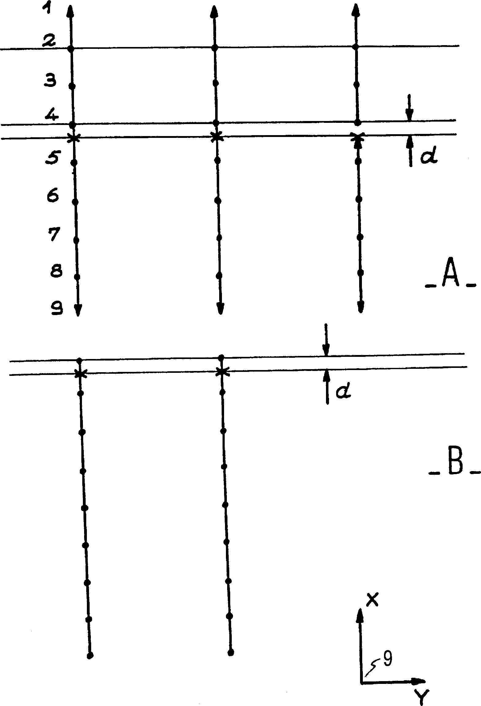
[0037] image 3 is to illustrate the difference due to the algebraically added noise voltage. That is, representing nine different nominal positions of the ink droplets formed by the pulses of the ink droplets in a marked frame, and representing the different shapes on the plane of the media represented by the XY axis. In order to make the explanation easy to understand, nine ink droplets are shown in this embodiment, and their intervals are enlarged.

[0038] exist image 3 In part A of the three frames, nine ink droplets numbered 1 to 9 are represented as dots at their nominal positions. These three frames form part of the same stripe A. It is assumed that there is a systematic deviation of the actual position of the ink drop 4 towards the ink drop 5 . The actual position is represented in the form of a cross. The distance d between the actual position and the nominal position of the ink droplet in row 4 results in a image 3 The white misalignment defect in part A is ...


PUM


Abstract

Process for modification of the position at which electrically-charged ink droplets arrive on a substrate (27), the droplets being charged by charge electrodes (20) connected to a voltage generator, the paths of the droplets being affected by the action of deviation electrodes (23, 24) that deviate the droplets depending on the value of their electrical charge, between N positions defining a frame obtained by a burst of droplets in the form of a straight segment approximately parallel to an X direction along which the substrate advances, process characterized in that an additional random voltage equal to a fraction less than 1 of the difference between the nominal voltages to be applied to the charge electrodes for each droplet and for one of the two immediately adjacent droplets in the frame, is applied in addition to a nominal voltage to be applied to each droplet charging means.

Description

technical field [0001] The present invention relates to an ink jet printer in which ink droplets are formed and charged and projected obliquely onto a print medium. It relates to a method of masking or reducing misalignment defects and a printer using this method. Background technique [0002] It is known that a pressurized drop of ink is ejected from a nozzle and then split into many individual droplets, each of which is charged separately in a controlled manner. A fixed potential electrode along the path of the separately charged ink droplets deflects the ink droplet by a variable amount that depends on how charged the ink droplet is. If the ink drop does not need to reach the print medium, its charging is controlled to deflect to an ink reclaimer. The working principle of such ink jet printers is well known and is described, for example, in US Patent A-4160982. As described in that patent and shown in FIG. 1 , a printer of this type includes an ink reservoir 11 contain...

Claims


Application Information

Patent Timeline
Patent Type & Authority Patents(China)
IPC IPC(8): B41J2/02B41J2/075B41J2/08B41J2/01B41J2/085B41J2/12B41J2/21B41J29/393
CPCB41J2/08B41J29/393B41J2/085B41J2/2132
Inventor A·杜南德
Owner MARKEM IMAJE HLDG
Features
  • R&D
  • Intellectual Property
  • Life Sciences
  • Materials
  • Tech Scout
  • Unparalleled Data Quality
  • Higher Quality Content
  • 60% Fewer Hallucinations
Learn More