Synthetic ripple regulator

a ripple regulator and ripple technology, applied in the direction of dc-dc conversion, power conversion systems, instruments, etc., can solve the problems of reducing power conversion efficiency, output voltage overshoot, and difficulty in maintaining tight dc regulation, so as to reduce output ripple and simplify compensation

Inactive Publication Date: 2006-11-07
INTERSIL INC
View PDF16 Cites 77 Cited by
  • Summary
  • Abstract
  • Description
  • Claims
  • Application Information

AI Technical Summary

Benefits of technology

[0010]A synthetic ripple voltage generator for a DC-DC regulator according to an exemplary embodiment of the present invention includes a transconductance amplifier circuit and a ripple capacitor. The DC-DC regulator includes a hysteretic comparator which develops a pulse width modulation (PWM) signal provided to a switching circuit that switches an input voltage via a phase node through an output inductor to develop an output voltage at an output node. The transconductance amplifier circuit has an input for coupling to the output inductor and an output coupled to the ripple capacitor and for coupling to an input of the hysteretic comparator. In this manner, the transconductance amplifier circuit monitors voltage applied to the output inductor and supplies an inductor voltage-representative current to the ripple capacitor, which produces the synthetic ripple voltage. Using the replicated inductor current for ripple regulation results in low output ripple, input voltage feed forward, and simplified compensation.

Problems solved by technology

Since the hysteretic comparator directly sets the magnitude of the ripple voltage, employing a smaller hysteresis voltage reduces the power conversion efficiency, as switching frequency increases with smaller hysteresis.
Since the ripple voltage wave shape varies with input line and load conditions, maintaining tight DC regulation is difficult.
This causes the output voltage to overshoot the hysteretic threshold, and results in higher peak-to-peak ripple.
As a result, the very improvements that were intended to lower the output voltage ripple in DC-DC regulators can actually cause increased ripple when used in a ripple regulator.

Method used


Image

  • Synthetic ripple regulator
  • Synthetic ripple regulator
  • Synthetic ripple regulator

Examples


Embodiment Construction

[0027]The following description is presented to enable one of ordinary skill in the art to make and use the present invention as provided within the context of a particular application and its requirements. Various modifications to the preferred embodiment will, however, be apparent to one skilled in the art, and the general principles defined herein may be applied to other embodiments. Therefore, the present invention is not intended to be limited to the particular embodiments shown and described herein, but is to be accorded the widest scope consistent with the principles and novel features herein disclosed.

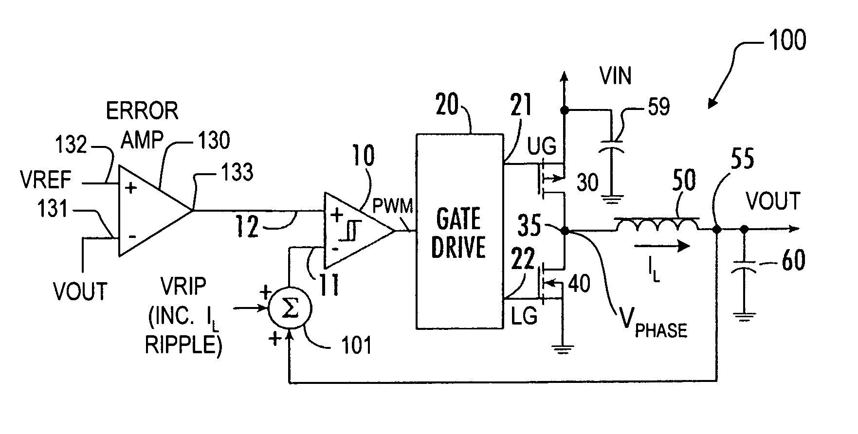
[0028]FIG. 1 is a schematic diagram of a synthetic ripple regulator 100 implemented according to an exemplary embodiment of the present invention including a summation unit 101 that adds a synthetic ripple voltage VRIP in the feedback control path. The synthetic ripple regulator 100 employs a hysteresis comparator 10 that controls a gate drive circuit 20 with respective output ...


PUM


Abstract

A synthetic ripple regulator including a synthetic ripple voltage generator that generates a synthetic ripple voltage indicative of the ripple current through an output inductor. The regulator uses the synthetically generated ripple voltage to control toggling of a hysteretic comparator for developing the pulse width modulation (PWM) signal that controls switching of the regulator. In a non-limiting implementation, a transconductance amplifier monitors the phase node voltage of the inductor and supplies an inductor voltage-representative current to a ripple capacitor, which produces the synthetic ripple voltage. Using the replicated inductor current for ripple regulation results in low output ripple, input voltage feed forward, and simplified compensation.

Description

CROSS-REFERENCE TO RELATED APPLICATIONS[0001]This application is a continuation-in-part of commonly assigned U.S. patent application Ser. No. 10 / 236,787, filed on Sep. 6, 2002 now U.S. Pat. No. 6,791,306, which is herein incorporated by reference for all intents and purposes.BACKGROUND OF THE INVENTION[0002]1. Field of the Invention[0003]The present invention relates to powers supply circuits and related components, and is particularly directed to a DC-DC regulator including a synthetic ripple voltage generator which generates an artificial or synthesized ripple waveform that controls the switching operation of the regulator, reduces output ripple and improves DC accuracy.[0004]2. Description of the Related Art[0005]Electrical power for integrated circuits is typically supplied by one or more direct current (DC) power sources. In a number of applications the circuit may require multiple regulated voltages that are different from he available supply voltage (which may be relatively l...

Claims


Application Information

Patent Timeline
Patent Type & Authority Patents(United States)
IPC IPC(8): G05F1/40H02M3/156
CPCH02M3/156
Inventor WALTERS, MICHAEL M.MURATOV, VLADIMIRWIKTOR, SEFAN WLODZIMIERZ
Owner INTERSIL INC
Why Eureka
Try Eureka