
Voltage conversion device

a voltage conversion device and voltage technology, applied in the direction of electric variable regulation, process and machine control, instruments, etc., can solve the problems of poor voltage conversion efficiency, energy to be wasted, voltage conversion device limit the application of load, etc., and achieve low output ripple and high power factor

Active Publication Date: 2016-11-22
DELTA ELECTRONICS INC
View PDF15 Cites 0 Cited by
  • Summary
  • Abstract
  • Description
  • Claims
  • Application Information

AI Technical Summary

Benefits of technology

The patent describes an application that allows for the creation of a voltage conversion device that has a high power factor and low output ripples. This means that the device can manage large amounts of power efficiently, and produce consistent and reliable output.

Problems solved by technology

A low power factor results in poor voltage conversion efficiency, causing energy to be wasted.
In addition, large output ripples of the voltage conversion device limit the applications of the load coupled to the voltage conversion device (e.g., if the load is a light-emitting diode, the ripples may cause flicker).
However, such a patent application is silent with respect to suppress output ripples.

Method used


Image

  • Voltage conversion device
  • Voltage conversion device
  • Voltage conversion device

Examples


Embodiment Construction

[0042]Reference will now be made in detail to the present embodiments of the invention, examples of which are illustrated in the accompanying drawings. Wherever possible, the same reference numbers are used in the drawings and the description to refer to the same or like parts.

[0043]It will be understood that, in the description herein and throughout the claims that follow, when an element is referred to as being “connected” or “electrically coupled” to another element, it can be directly connected or coupled to the other element, or intervening elements may be present. In contrast, when an element is referred to as being “directly connected” to another element, there are no intervening elements present. Moreover, “connect” or “electrically connect” can further refer to the interoperation or interaction between two or more elements.

[0044]It will be understood that, in the description herein and throughout the claims that follow, although the terms “first,”“second,” etc. may be used ...


PUM


Abstract

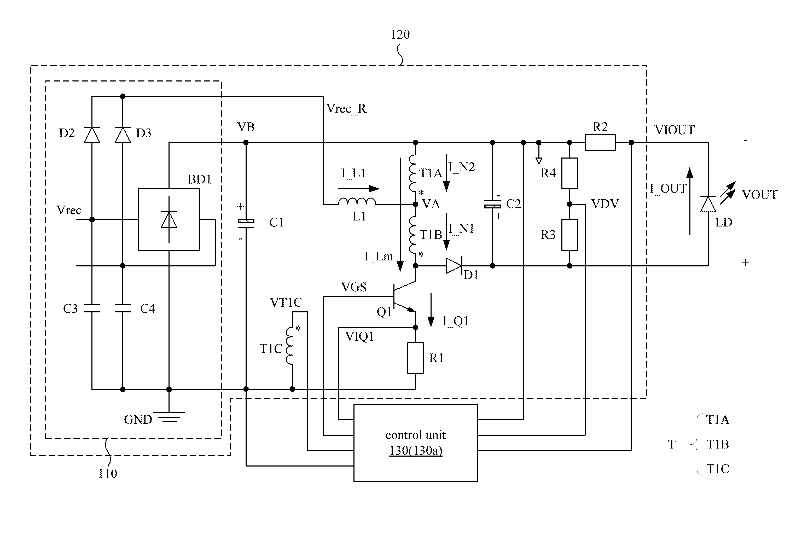
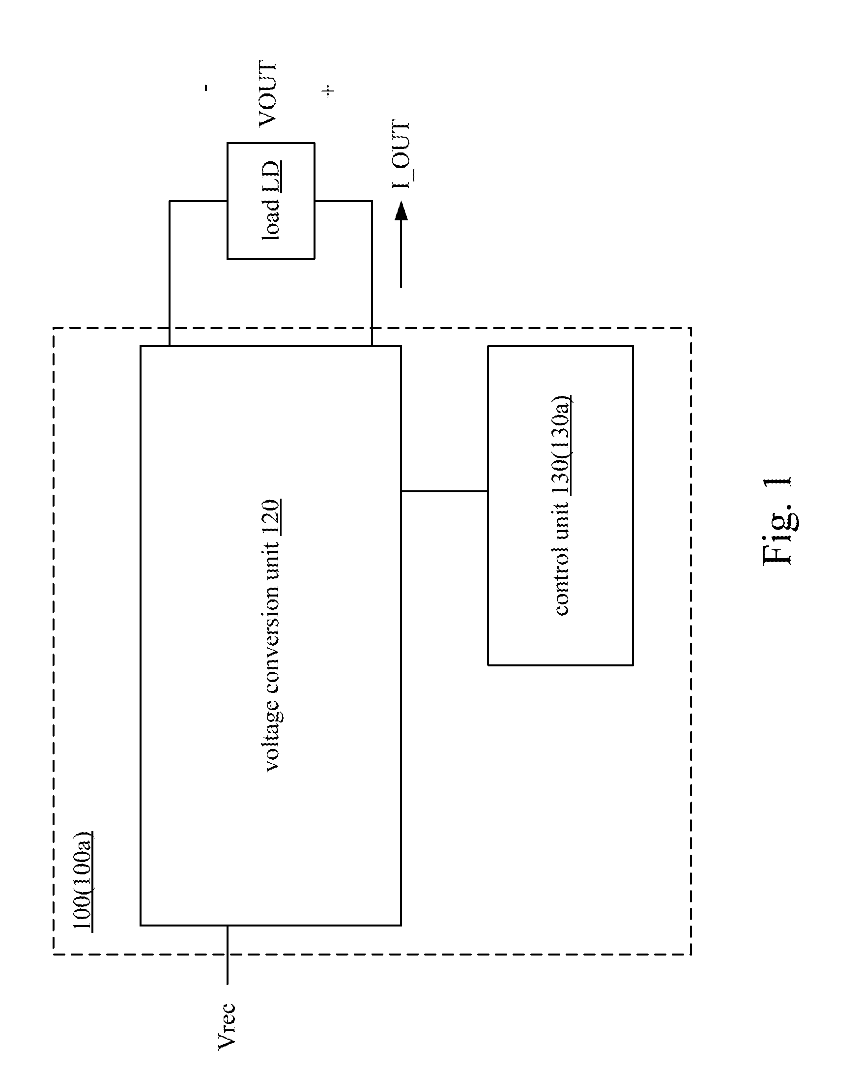
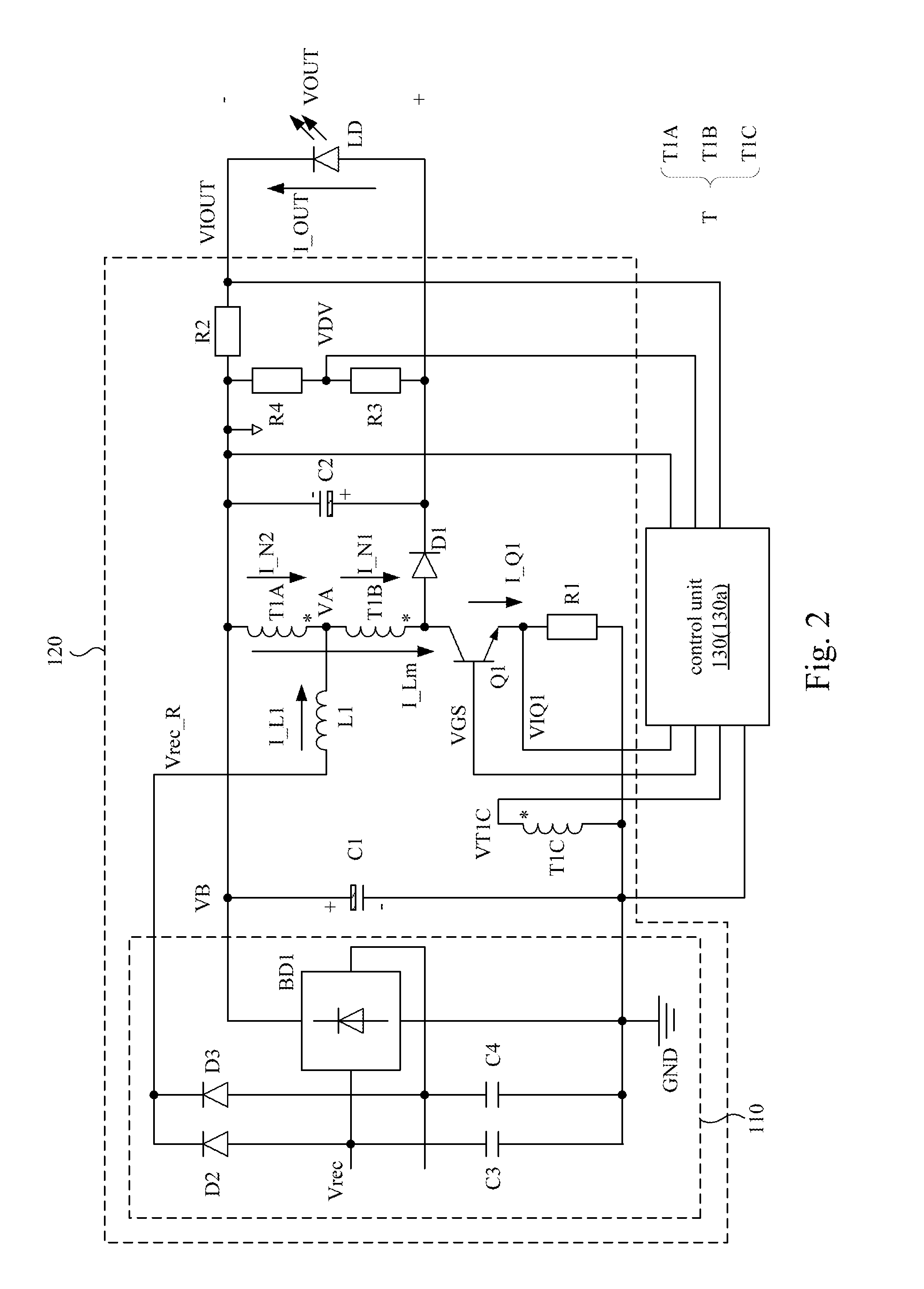
A voltage conversion device includes a voltage conversion unit and a control unit. The voltage conversion unit includes an input rectifier circuit, a storage capacitor, a storage inductor, a transformer, a switch, and a rectifier component. A first end of the storage inductor is electrically coupled to a first output end of the input rectifier circuit. A first end of the transformer is electrically coupled to a second output end of the input rectifier circuit. A second end of the transformer is electrically coupled to a second end of the storage inductor. The switch is electrically coupled to a third end of the transformer. The control unit is configured to provide a control signal to the switch according to a current passing through the switch and at least one of an output voltage and an output current.

Description

RELATED APPLICATIONS[0001]This application claims priority to Chinese Application Serial Number 201510177724.8, filed Apr. 15, 2015, which is herein incorporated by reference.BACKGROUND[0002]Technical Field[0003]The present disclosure relates to an electronic device. More particularly, the present disclosure relates to a voltage conversion device.[0004]Description of Related Art[0005]With advances in technology, voltage conversion devices have been widely used.[0006]A typical voltage conversion device can convert an AC voltage to a steady DC voltage. The power factor of the voltage conversion device affects the voltage conversion efficiency. A low power factor results in poor voltage conversion efficiency, causing energy to be wasted. In addition, large output ripples of the voltage conversion device limit the applications of the load coupled to the voltage conversion device (e.g., if the load is a light-emitting diode, the ripples may cause flicker).[0007]United States Patent Appli...

Claims


Application Information

Patent Timeline
Patent Type & Authority Patents(United States)
IPC IPC(8): H05B39/00H02M3/335H05B33/08H05B44/00
CPCH02M3/33515H05B33/0815H02M1/15H02M1/4208H02M7/08H05B45/10Y02B20/30Y02B70/10H05B45/3725H02M1/0064H02M1/4275H02M1/4291
Inventor FU, XIAO-PINGZHANG, XING-HUA
Owner DELTA ELECTRONICS INC
Learn More