High voltage DC power supply for high power radio frequency amplifiers

a high-voltage dc power supply and amplifier technology, applied in the direction of electric variable regulation, process and machine control, instruments, etc., can solve the problems of reducing the control bandwidth, generating substantial line harmonics, and significant deterioration of the input power factor,

Inactive Publication Date: 2018-07-17
THE SEC
View PDF4 Cites 4 Cited by
  • Summary
  • Abstract
  • Description
  • Claims
  • Application Information

AI Technical Summary

Benefits of technology

[0023]It is another object of the present invention is to provide an input section that has lower input harmonics enabling the utility supply to cater to the requirement of other nonlinear loads without exceeding specified standard harmonics limit.
[0024]It is another object of the present invention is to provide a topology of high voltage DC power supply that has flexibility for increasing the output voltage to higher value by adding number of switch power modules in series.
[0025]It is another object of the present invention to provide a high voltage DC power supply system where eight out of seventy two numbers of switch power modules are kept as active redundant to improve the system reliability.
[0026]It is yet another object of the present invention is to provide a high-voltage power supply that has a full range 24 pulsed input systems with inherently low input harmonics and high input power factor making it suitable for high power applications.
[0027]It is still another object of the present invention is to provide a high voltage regulated DC power supply that is either ripple free or have low output ripple, low output stored energy, crowbar less, high output stability, high overall efficiency, high system reliability and availability.

Problems solved by technology

High power radio frequency (RF) amplifiers demand stringent performances from their bias power supplies.
Most of these requirements are contradictory in nature.
But RF amplifiers are sensitive to stored energies during internal flashover, arcing, etc., and can handle maximum up to 20 Joules of stored energy, the realization of which is a major challenge to the designer.
Bigger ripple filters also reduces control bandwidth deteriorating output voltage stability.
Another challenge encountered with high power regulated DC power supplies is the generation of substantial line harmonics as well as significant deterioration of the input power factor.
But they are inherently non-linear, generating harmonics current in the line as well as deteriorating the input power factor significantly.
However, the scheme stores substantial energy in their output ripple filter 16 even after cutting off the input supply, requiring suitable crowbar 17 to bypass these stored energies for protecting the sensitive RF amplifier, under any unfavorable conditions.
Furthermore, AC regulator control also increases the line harmonics and deteriorates the input power factor significantly discouraging its use for high power applications
However, this scheme stores substantial energy in the primary bridge inductors 27 and 28, which needs to be dissipated under unfavorable conditions.
However, the said scheme employs multi secondary transformers 41 and 42, which are difficult to fabricate.
The control of this power supply is on high voltage side, which demands complex sensing as well as costly fibre optics based communication system.
In addition, parasitic capacitances in the secondary windings of multi secondary transformers 45 and 46 are charged up to the highest voltage in the system, which hardly find any paths for their discharges in spite of tripping module switchgears and IGBTs 49 under any unfavorable situations leaving high voltage safety related issues.
Thus, the drawback of conventional topologies of the controlled DC power supplies is that the control of output voltage affects both input performance parameters like input line harmonics, input power factors as well as output performance parameters like output ripple, output stored energy.
Also, most of the schemes adopted for similar applications are either 6 pulsed or 12 pulsed and the line harmonics generated by them increases with increase in the control range deteriorating the input power factor significantly.
These values also increase further under practical conditions, along with the generation of some amount of 5th and 7th harmonics causing problem in limiting the line harmonics below that specified in the IEEE Std 519-1992.

Method used


Image

  • High voltage DC power supply for high power radio frequency amplifiers
  • High voltage DC power supply for high power radio frequency amplifiers
  • High voltage DC power supply for high power radio frequency amplifiers

Examples


example 1

em Reliability with Active Redundancy

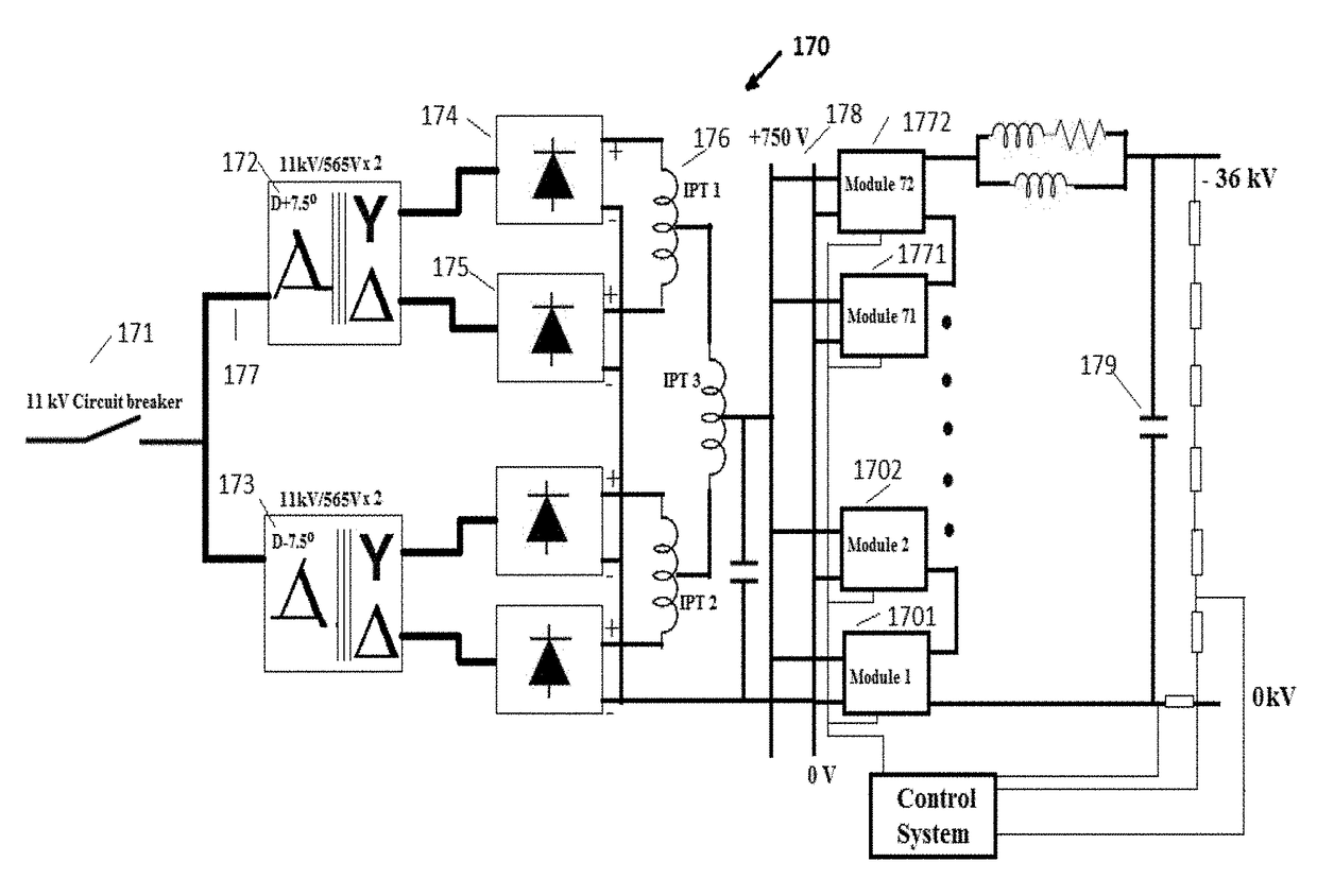
[0099]Eight out of seventy two numbers of power modules are intentionally kept as active redundant in the power supply so that failure of up to eight power modules will not affect the operation of RF amplifier.

[0100]The probability of failure of “i” units out of total “N” units is given as

P(i)=NCi(1−p)ipN-i

[0101]Where p=reliability of individual unit

NCi=N! / (i!×(N−i)!)

[0102]Taking reliability of individual power modules to be 95%, the probability of failure of up to eight power modules are estimated as under.

[0103](a) The probability that all 72 power modules will work well is given by

P(0)72C0(1−p)0p72=0.0249

[0104](b) The probability of failure of one power module out of 72 is given by

P(1)=72C1(1−p)1p71=0.0943

[0105](c) The probability of failure of two power modules out of 72 is given by

P(2)=72C2(1−p)2p70=0.1762

[0106](d) The probability of failure of three power modules out of 72 is given by

P(3)=72C3(1−p)3p69=0.2164

[0107](e) The probability of fa...

example 2

ibility for Higher Output Voltage

[0115]The present supply scheme has wide flexibility in increasing the output voltage to higher value by adding number of DC-DC power modules 130 in series, without requiring any modifications in the existing power modules. High voltage isolation may be provided in the transformers 138 of DC-DC power modules to be floated at higher voltage. Input section also needs no modification as long as total power drawn is within its full power rating. This is a unique feature of the present supply scheme as no other prior art scheme provide flexibilities in increasing the output voltage, as common isolation between input and output is provided by its main transformer.

example 3

ith IOT Amplifier

[0116]The present power supply is tested at −36 kV, 4.5 Amp on an E2V make, IOTD2130 Inductive Output Tube (TOT) RF amplifier and the experimental results obtained are presented. The input system always remains 24 pulsed for the entire range of the operation of this power supply. FIG. 6 shows a 24-pulse input line current waveform in L2 phase and FIG. 7 shows its frequency spectrum with predominant 23rd and 25th harmonics 71 and 72, which are near to the expected ideal waveform. All IGBTs 134 to 137 in the inverter bridge of power modules are operated in zero voltage switching modes over the entire operating range. It is observed that the DC-DC module output has voltage overshoots, which affect the output performance and was reduced by putting a small capacitor across the rectified output. A diode is placed in series with the capacitor for not allowing its stored energy to be dumped into the RF amplifier under any arcing conditions. Experimental voltage 211 and curr...


PUM


Abstract

The present invention provides a high voltage regulated DC power supply with full range 24 pulse input for ripple free output for high power RF amplifier, comprising: full range 24 pulse 3 phase 11 kV input system configured to provide uncontrolled low voltage DC bus, low input harmonics and high input power factor; a plurality of DC-DC power modules having their output connected in a series and coupled to the said DC bus voltage; each power module comprising a DC source, an inverter bridge IGBTs operating at predefined duty cycle and staggered to reduce the output ripple and output stored energy; and a combination of feed forward and feedback control circuit adapted to regulate the variations in the input line voltage and the variation in output at various load current to finally obtain ripple free high voltage output.

Description

TECHNICAL FIELD OF THE INVENTION[0001]The present invention relates to high voltage DC power supply system for RF amplifiers and more particularly to a high voltage DC power supply with full range 24 pulsed input and ripple free output for RF amplifiers comprising a plurality of DC power modules connected in series to provide −36 kV regulated DC output.BACKGROUND OF THE INVENTION[0002]High power radio frequency (RF) amplifiers demand stringent performances from their bias power supplies. Tighter output voltage regulations with better stability, lower output ripples, lower stored energies etc., are some of the output performance requirements and lower input harmonics, better Input Power Factors (IPF) etc., are crucial input performance requirements of these power supplies. Most of these requirements are contradictory in nature. For example, in high power regulated DC power supplies, the output ripple increases with the increase in control range of output voltages requiring bigger rip...

Claims


Application Information

Patent Timeline
Patent Type & Authority Patents(United States)
IPC IPC(8): H02J1/00H02M7/08H03F3/19H03F1/02H02M7/5387H02M3/335H02J3/36H02J3/00H02M1/42H02M3/337H02M1/12H02M1/00
CPCH02J3/36H02M1/12H02M1/4216H02M3/337H02M3/33507H02M7/08H03F1/0238H03F3/19H02M7/53871H03F2200/451H02J2003/365H02M2001/007H02M2001/0016H02M2001/0077Y02B70/10H02M1/0016H02M1/0077H02M1/007H02M3/33573
Inventor BADAPANDA, MANMATH KUMAR
Owner THE SEC
Why Eureka
Try Eureka