Output voltage compensating circuit and method for a floating gate reference voltage generator

a reference voltage and output voltage technology, applied in the field of analog reference voltage generators, can solve the problems of net negative charge on floating gate fg, limited circuit b>70/b> accuracy, and prior art reference voltage generator circuits typically do not compensate for voltage drops, so as to improve the accuracy of voltage reference voltage

Inactive Publication Date: 2005-05-17
XICOR
View PDF15 Cites 81 Cited by
  • Summary
  • Abstract
  • Description
  • Claims
  • Application Information

AI Technical Summary

Benefits of technology

[0014]The present invention provides a system and method for adjusting the output voltage of a floating gate reference voltage generator circuit in order to improve the accuracy of the voltage reference voltage at the load of the floating gate reference voltage generator circuit.

Problems solved by technology

This results in a net negative charge on floating gate fg.
Second, the accuracy of circuit 70 is also limited because the potential of floating gate fg changes another 100 mV to 200 mV over time after it is set due to various factors, including detrapping of the tunnel devices and dielectric relaxation of all the floating gate fg capacitors.
In addition, prior art reference voltage generator circuits typically do not compensate for voltage drops due to resistances, i.e., current-resistance (IR) drops, that exist between a reference voltage generator circuit, typically in the form of an integrated circuit (IC) and a load circuit.
When the required accuracy of this output voltage is much higher, in the range of ±1 mV or better, for example, the IR drop between the reference voltage generator circuit and the load circuit may contribute significantly to the amount of error in the value of the reference voltage that exists at the input terminal of the load circuit.
One or more of the above described three IR drops are not typically compensated for in the prior art.

Method used


Image

  • Output voltage compensating circuit and method for a floating gate reference voltage generator
  • Output voltage compensating circuit and method for a floating gate reference voltage generator
  • Output voltage compensating circuit and method for a floating gate reference voltage generator

Examples


Embodiment Construction

[0040]The present invention is an apparatus and a method for the compensation of a voltage drop created in a conductive path from an output terminal of a high precision reference voltage generator circuit to an input terminal of a load. A better understanding of the present invention will be gained by the following description of the preferred embodiments of the present invention.

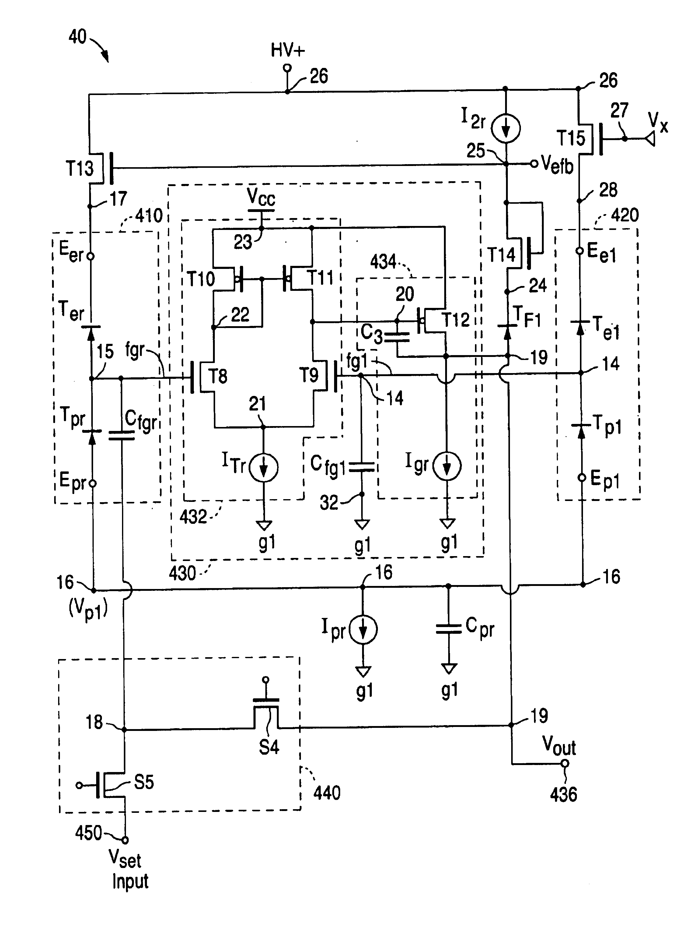
[0041]FIG. 3 is a circuit diagram of a differential single floating gate circuit 30 according to the present invention for accurately setting a floating gate to analog voltage during a high voltage set mode or set cycle. FIG. 4A is a circuit diagram of a differential dual floating gate circuit 40 according to another embodiment of the present invention. Circuit 40 is also used to accurately set a floating gate to an analog voltage during a high voltage set mode. Once the analog voltage level is set, both circuit 30 and circuit 40 can then be configured during a read mode as a precise voltage comparator circ...


PUM


Abstract

An apparatus and method is provided for adjusting a reference voltage at an output terminal of a floating gate reference voltage generator circuit in order to improve the accuracy of the reference voltage at an input terminal of a load circuit. The apparatus and method compensates for the voltage drop produced between the output terminal of the reference voltage generator circuit and the input terminal of the load circuit, and includes a capacitor for capacitively coupling the voltage at the input terminal of said load circuit to a floating gate, and a differential amplifier operatively coupled to the floating gate which acts in response to the capacitively coupled load circuit input voltage to adjust the voltage at the output terminal such that the voltage at the input terminal of the load circuit becomes equal to the reference voltage.

Description

FIELD OF THE INVENTION[0001]The invention relates generally to the field of analog reference voltage generators and in particular to improving accuracy of the voltage supplied by a floating gate reference voltage generator circuit to a load.BACKGROUND OF THE INVENTION[0002]Programmable analog floating gate circuits have been used since the early 1980's in applications that only require moderate absolute voltage accuracy over time, e.g., an absolute voltage accuracy of 100-200 mV over time. Such devices are conventionally used to provide long-term non-volatile storage of charge on a floating gate. A floating gate is an island of conductive material that is electrically isolated from a substrate but capacitively coupled to the substrate or to other conductive layers. Typically, a floating gate forms the gate of an MOS transistor that is used to read the level of charge on the floating gate without causing any leakage of charge therefrom.[0003]Various means are known in the art for int...

Claims


Application Information

Patent Timeline
Patent Type & Authority Patents(United States)
IPC IPC(8): G05F3/26G05F3/08
CPCG05F3/262
Inventor OWEN, WILLIAM H.
Owner XICOR
Why Eureka
Try Eureka