
Household monitoring equipment and monitoring method thereof

A technology for monitoring equipment and home use, which is applied in the direction of TV, telephone communication, color TV parts, etc., which can solve the problems of low practicability, less monitoring equipment, and deformation of shooting quality, so as to facilitate storage and processing, and facilitate design. The effect of setting and controlling

Pending Publication Date: 2021-12-10
王磊
View PDF0 Cites 0 Cited by
  • Summary
  • Abstract
  • Description
  • Claims
  • Application Information

AI Technical Summary

Problems solved by technology

[0003] In the process of installation and use, it is found that most of the existing monitoring equipment are office and outdoor monitoring equipment, and there are few monitoring equipment suitable for home use. The existing monitoring equipment can only record audio and video, and cannot be seen by family members. In the event of an accident, make a subjective response plan, which is less practical;
[0004] In the household monitoring equipment in the existing patent technology, such as CN2021105103682, a single camera and a hinged connection structure are used to realize shooting from various angles, but it cannot achieve panoramic orientation coverage. If it is replaced with a spherical panoramic camera, it is prone to deformation of the shooting quality. In addition, for special scenes, it is necessary to shoot the same important picture from different angles, so that more information can be mined during playback comparison, and an excellent synchronization mechanism is required for multi-angle comparison shooting, and dynamic The rotation direction of the camera is used to track the dynamic picture, such as fighting scenes or theft, but the simple use of timing or remote synchronization is not reliable and requires a high-precision synchronization control module. Therefore, the existing home monitoring equipment is The above functions cannot be realized

Method used


Image

  • Household monitoring equipment and monitoring method thereof
  • Household monitoring equipment and monitoring method thereof
  • Household monitoring equipment and monitoring method thereof

Examples


Embodiment

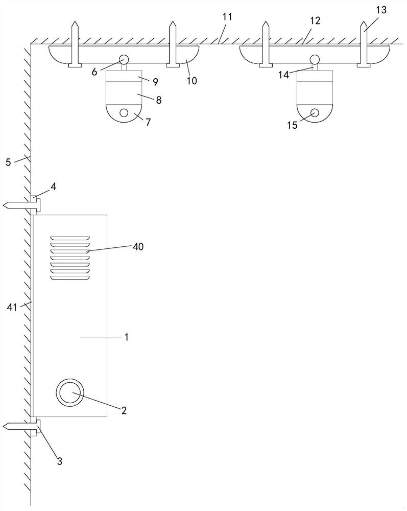
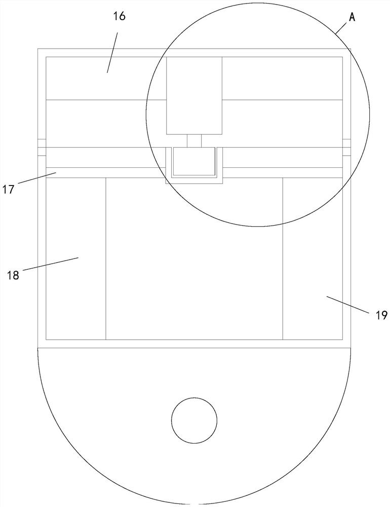
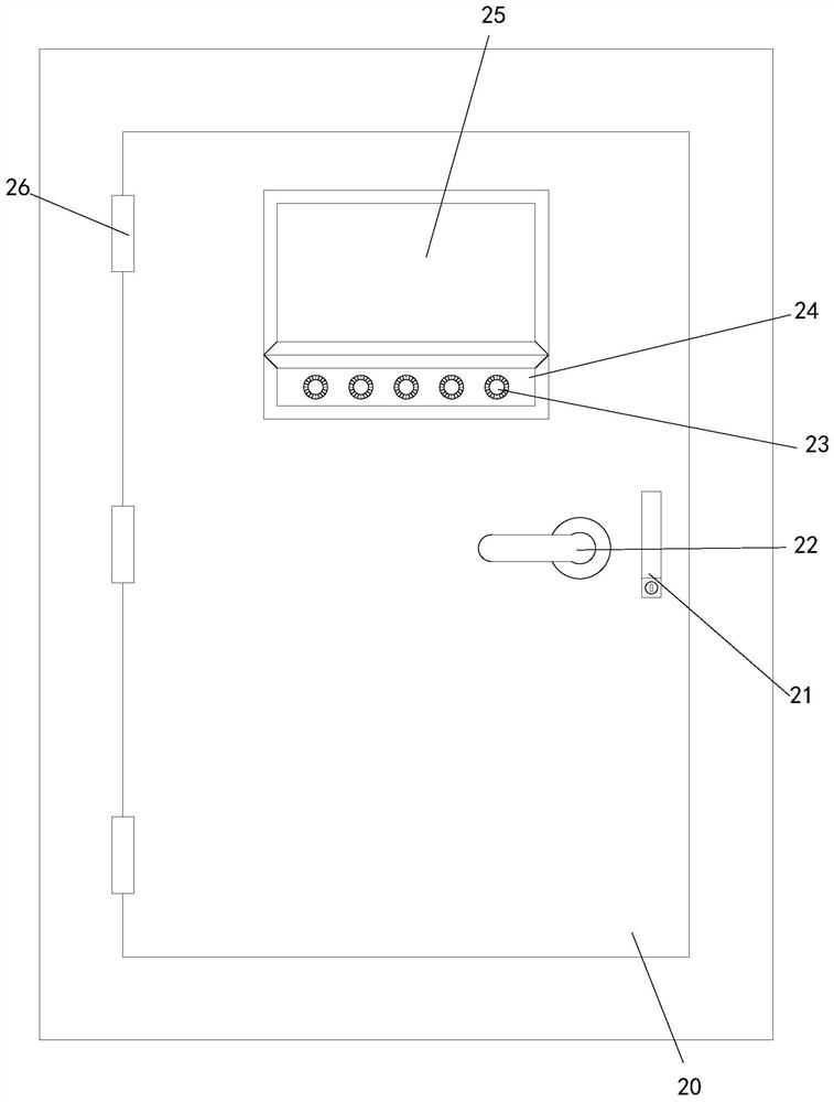
[0035] see Figure 1-6, a household monitoring device, comprising a wall 5, a top board 11, a control cabinet 1 and a camera body, the top of the wall 5 is fixedly connected to the bottom of the top board 11, and the top and bottom of the control cabinet 1 are set There is a connecting plate-4, the right end of each connecting plate-4 is provided with a fixed bolt-3, and the left end of each fixed bolt-3 passes through the right end of the wall body 5 and extends to the inside of the wall body 5, the control The right end of the cabinet 1 is provided with a first square hole, and the right end of the first square hole is connected with a door 20 through a group of hinges 26, the right end of the door 20 is provided with a display screen 25, and the lower end of the display screen 25 is provided with a control panel. box 24, and the right end of the control box 24 is provided with a plurality of control keys 23, a group of connecting rods 30 are connected between the front side...


PUM


Abstract

The invention relates to the technical field of monitoring, in particular to household monitoring equipment and a monitoring method thereof. The household monitoring equipment comprises a wall body, a top plate, a control cabinet and a camera shooting body, the top end of the wall body is fixedly connected with the bottom end of the top plate, first connecting plates are arranged at the top end and the bottom end of the control cabinet correspondingly, and a display screen is arranged at the right end of a blocking door; the lower end of the display screen is provided with a control box, the periphery of the right end of the backboard is provided with a wiring channel, the upper area of the right end of the backboard is provided with a control gate, the middle of the right end of the backboard is provided with a second network connector and an audio analyzer, and the lower area of the right end of the backboard is provided with a telephone traffic connector and an image analyzer. A second motor is arranged at one end of each third connecting plate, a ball groove is formed in the middle of the bottom end of the first fixing plate, and a rotating ball is arranged in the ball groove, so that the household monitoring equipment is suitable for household monitoring, subjective judgment is made and processing is carried out when family members have accidents, and the practicability is high.

Description

technical field [0001] The invention relates to the technical field of monitoring, in particular to a household monitoring device and a monitoring method thereof. Background technique [0002] As we all know, with the improvement of people's living standards and the popularization of the Internet, security protection has become more and more popular, especially in recent years, the development of information technology and the improvement of people's living environment have prompted unprecedented strengthening of people's awareness of family security. Home network video surveillance, by virtue of its technical seamless compatibility with IP network and the remote real-time video processing capability and other network applications, has rapidly become the fastest growing product in the market with an annual growth rate of 40%. Its market demand is unlimited. [0003] In the process of installation and use, it is found that most of the existing monitoring equipment are office...

Claims


Application Information

Patent Timeline
IPC IPC(8): H04N5/225H04N7/18H04M11/00
CPCH04N7/18H04M11/00H04N23/50
Inventor 王磊
Owner 王磊
Learn More