A fully automatic precise sealing device for polymer chips
A fully automatic, polymer technology, applied in the direction of laboratory equipment, laboratory containers, chemical instruments and methods, etc., can solve the problems of chip scalding and manual removal inconvenience, and achieve the effect of convenient manual operation and saving manpower
- Summary
- Abstract
- Description
- Claims
- Application Information
AI Technical Summary
Problems solved by technology
Method used
Image

Examples
Embodiment 1
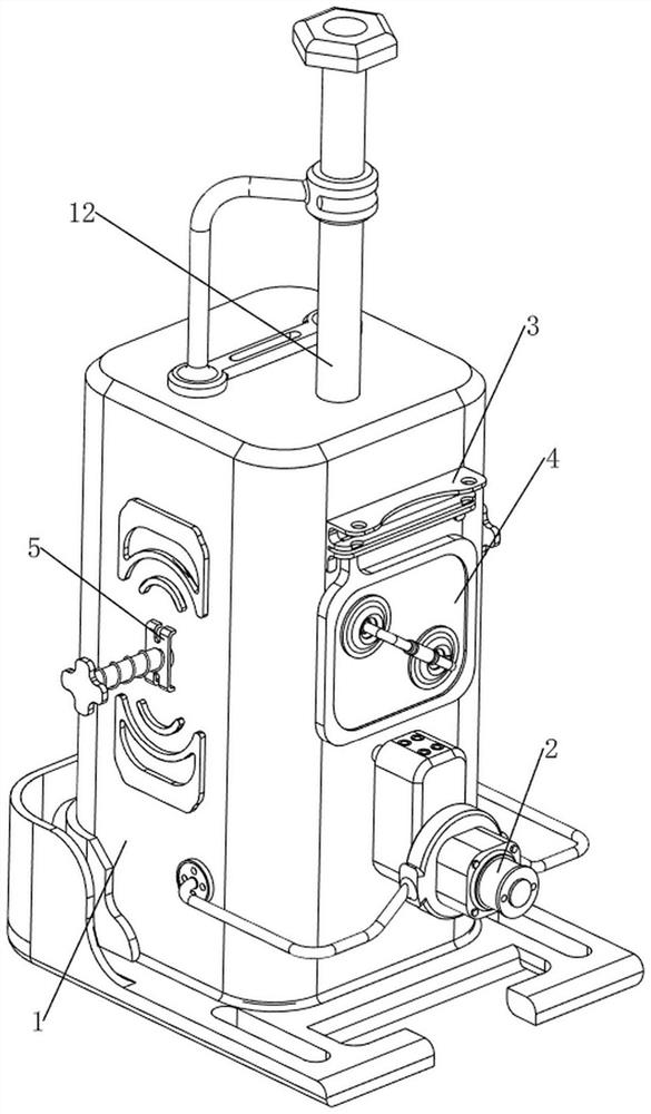
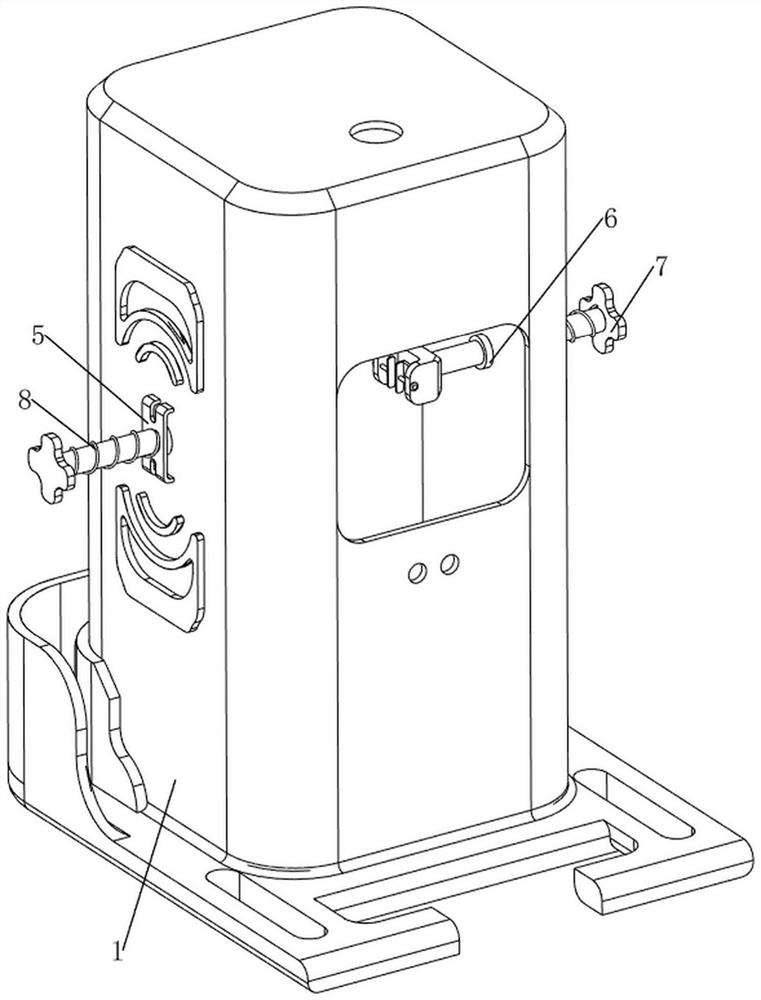
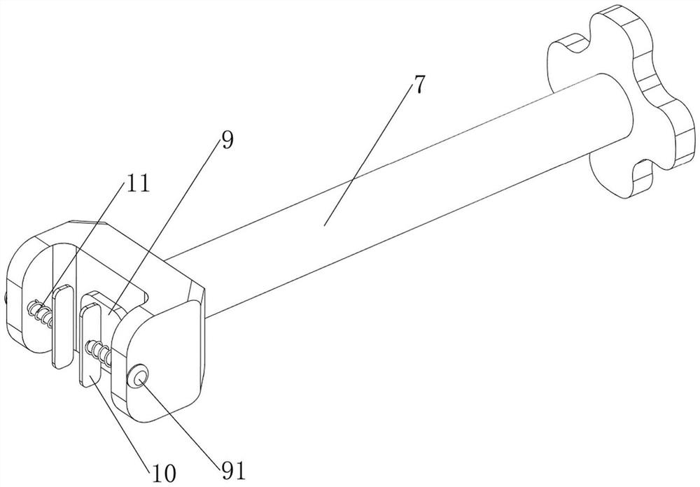
[0039] A fully automatic precise sealing device for polymer chips, such as Figure 1-9 As shown, it includes a casing 1, an air pump 2, a first fixed frame 3, a first movable plate 4, a first fixed plate 5, a sealing ring 6, a first movable rod 7, a first spring 8, a heating plate 9, a first Two movable rods 91, the first rubber plate 10, the second spring 11, the power mechanism 12 and the cooling mechanism 13, the air pump 2 is installed on the lower part of the front side of the shell 1, the air pump 2 communicates with the inside of the shell 1, and the upper part of the front side of the shell 1 is connected There is a first fixed frame 3, a first movable plate 4 is slidably connected to the first fixed frame 3, and a through hole is opened on the upper front side of the casing 1, the first movable plate 4 can block the through hole, and the user can pass through the through hole To place and take out the chip, the middle part of the left and right sides of the casing 1 i...
Embodiment 2
[0044] On the basis of Example 1, such as Figure 4 , Figure 9 , Figure 10 , Figure 11 , Figure 12 and Figure 13 As shown, a moving mechanism 14 is also included, and the moving mechanism 14 is used to assist the movement of the third movable plate 137. The moving mechanism 14 includes a third bracket 141, a first rotating shaft 142, a one-way gear 143, a first gear 144, a second A fixed rod 145, the first rack 146, the fourth spring 147, the contact rod 148 and the second rack 149, the inner bottom of the shell 1 is connected with the third bracket 141 and the first fixed rod 145, the first fixed rod 145 is located at the second The rear side of the three brackets 141, the top of the third bracket 141 is rotatably connected with the first rotating shaft 142, the first rotating shaft 142 is connected with the one-way gear 143 and the first gear 144, the one-way gear 143 is located on the left side of the first gear 144, the second The upper part of a fixed rod 145 is...
Embodiment 3
[0049] On the basis of Example 2, such as Figure 4 , Figure 11 , Figure 13 , Figure 14 and Figure 15 Shown, also comprise disengagement mechanism 16 and connecting mechanism 17, be provided with disengagement mechanism 16 between movable frame 155, the first rotating rod 153 and the 3rd movable plate 137, the second fixed rod 152, the first rotating rod 153 and the 3rd movable plate A connecting mechanism 17 is provided between the two rotating rods 154 , and the cooperation between the disengaging mechanism 16 and the connecting mechanism 17 can drive the first rotating rod 153 and the second rotating rod 154 to rotate.
[0050] Disengagement mechanism 16 comprises the fifth spring 161, push block 162, second fixed frame 163, the sixth spring 164 and movable block 165, is covered with the fifth spring 161 on the movable frame 155, and the fifth spring 161 two ends are respectively connected in movable On the frame 155 and the third fixed plate 151, a push block 162 i...
PUM
 Abstract
Description
Claims
Application Information
 - R&D
- Intellectual Property
- Life Sciences
- Materials
- Tech Scout
- Unparalleled Data Quality
- Higher Quality Content
- 60% Fewer Hallucinations
Browse by: Latest US Patents, China's latest patents, Technical Efficacy Thesaurus, Application Domain, Technology Topic, Popular Technical Reports.
© 2025 PatSnap. All rights reserved.Legal|Privacy policy|Modern Slavery Act Transparency Statement|Sitemap|About US| Contact US: help@patsnap.com