Metal part forming equipment

A technology for forming equipment and metal parts, which is applied in the field of forming equipment for screw forming, and can solve the problems of heavy oil pollution on the conveyor belt surface and residual cooling oil, etc.

Pending Publication Date: 2021-12-17
上海春日机械工业有限公司
View PDF0 Cites 0 Cited by
  • Summary
  • Abstract
  • Description
  • Claims
  • Application Information

AI Technical Summary

Problems solved by technology

[0003] After the screw forming is completed, the screw needs to be discharged to the conveyor belt in time. However, since the screw will leave cooling oil after forming, the cooling oil will be brought to the conveyor belt surface when it is transported to the conveyor belt, causing the conveyor belt surface to be damaged. heavily oily

Method used


Image

  • Metal part forming equipment
  • Metal part forming equipment
  • Metal part forming equipment

Examples


Embodiment Construction

[0030] Attached below Figure 1-3 The present invention is further illustrated with specific examples.

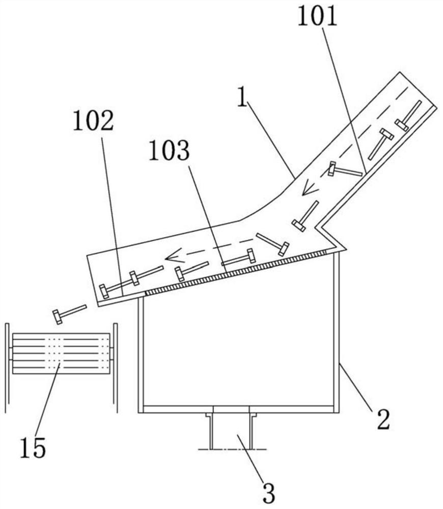
[0031] Such as figure 1 As shown, a metal part forming equipment includes a blanking guide seat 1 set on the blanking side of the equipment, and a conveyor belt 15 for conveying screws, which is directly below the discharge port on the lower side of the blanking guide seat 1. The material guide seat 1 is provided with a guide groove for guiding the sliding direction of the screw.

[0032] The guide groove bottom surface of the above-mentioned blanking guide seat 1 includes:

[0033] A first inclined bottom surface 101 inclined downward along the blanking direction;

[0034] The second inclined bottom surface 102 inclined downward along the blanking direction, the highest end of the second inclined bottom surface 102 is directly below the lowest end of the first inclined bottom surface 101, the lowest end of the second inclined bottom surface 102 is directly above the con...


PUM


Abstract

The invention discloses metal part forming equipment. The metal part forming equipment comprises a material falling guide seat and a conveying belt. The bottom surface of a guide groove of the material falling guide seat comprises a first inclined bottom surface which is inclined downwards in the material falling direction; a second inclined bottom surface which is inclined downwards in the material falling direction, wherein the gradient of the second inclined bottom surface is smaller than that of the first inclined bottom surface; and an oil draining net which is positioned in the range of the second inclined bottom surface and is used for directly receiving screws rolling down from the first inclined bottom surface, wherein an oil receiving tank which is provided with an opening in the upper side and is used for recycling waste oil is arranged under the material falling guide seat, and the oil draining net is directly butted with the opening in the upper side of the oil receiving tank. A cooling oil circulating system of the equipment comprises an oil discharging pipe, an oil liquid recycling box and an oil returning pipe which are sequentially arranged in the oil liquid flowing direction. The cooling oil can be recycled in the whole process.

Description

technical field [0001] The invention relates to the technical field of forming metal parts, in particular to a forming equipment for screw forming. Background technique [0002] At present, during the forming process of forming equipment for metal parts (for example, for screw forming), the cooling oil circulation system needs to be used to circulate the cooling oil to filter various impurities in the cooling oil. [0003] After the screw forming is completed, the screw needs to be discharged to the conveyor belt in time. However, since the screw will leave cooling oil after the screw is formed, it will bring the cooling oil to the conveyor belt surface when it is transported to the conveyor belt, resulting in Oil is heavy. Contents of the invention [0004] The object of the present invention is to provide a forming equipment for metal parts, which solves the problems in the prior art. [0005] The object of the present invention is achieved in the following way: a form...

Claims


Application Information

Patent Timeline
Patent Type & Authority Applications(China)
IPC IPC(8): B08B7/04B08B13/00B03C1/26
CPCB08B7/04B03C1/26B08B13/00
Inventor 彭军刘创
Owner 上海春日机械工业有限公司
Why Eureka
Try Eureka