Lifting hole cover plate of electric turnover structure

A technology of hanging object hole cover plate and flip structure, which is applied in the direction of power control mechanism, trap door, building components, etc., and can solve the problems of insufficient lifting height of lifting equipment, large hole size of hanging objects, and inability to lift out hanging parts, etc. , to achieve the effect of occupying equipment space, low manufacturing cost, and less assembly man-hours

Active Publication Date: 2021-12-17
江苏至善尚合电力科技有限公司
View PDF6 Cites 4 Cited by
  • Summary
  • Abstract
  • Description
  • Claims
  • Application Information

AI Technical Summary

Problems solved by technology

[0002] Due to the large size of some hanging object holes (for example: the length is usually 8 meters and the width is more than 3.2 meters); and the special requirements of the lifting operation or the door opening direction is limited, the door panels of the hanging object holes cannot be folded vertically and short-side. , and when the horizontal split is adopted, due to the large span of the door plank, a larger type of steel beam is required to support the self-weight and external load of the door plank, and the conventional split door technology (the door plank and the outer frame are connected by hinges) has a high When it exceeds 1.6 meters, it will not only affect the hoisting sight, but also cause the hanging parts to be unable to be lifted out due to the insufficient lifting height of the lifting equipment.

Method used


Image

  • Lifting hole cover plate of electric turnover structure
  • Lifting hole cover plate of electric turnover structure
  • Lifting hole cover plate of electric turnover structure

Examples


Embodiment Construction

[0027] The technical solutions in the embodiments of the present invention will be clearly and completely described below in conjunction with the accompanying drawings.

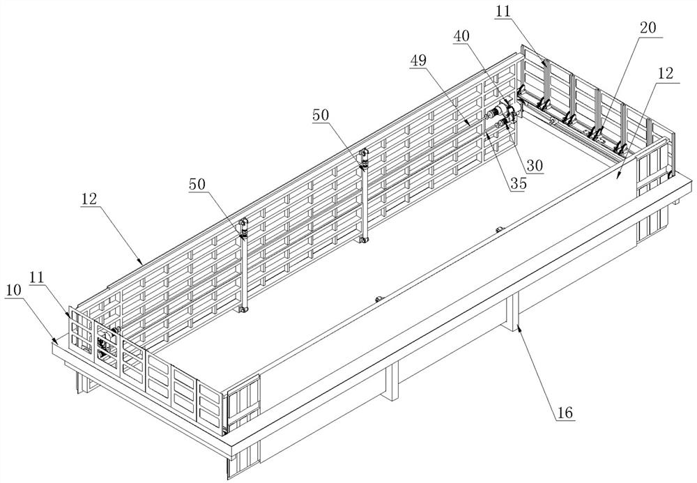
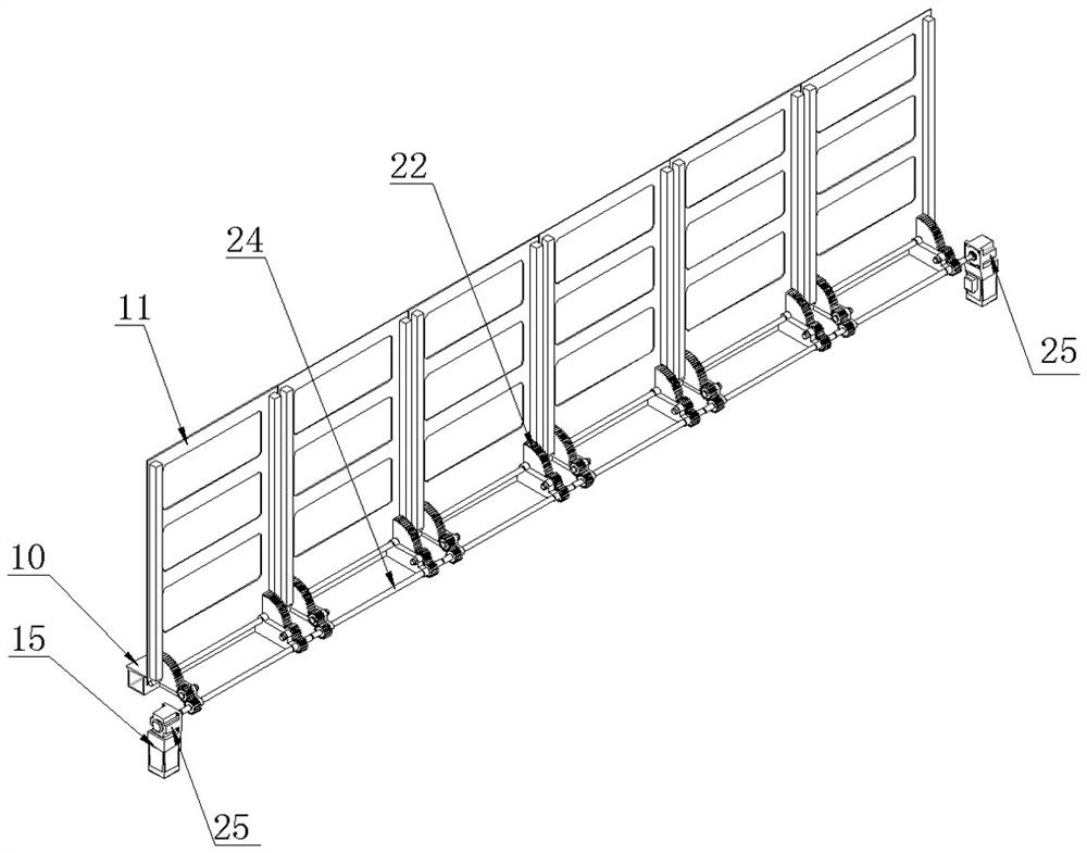
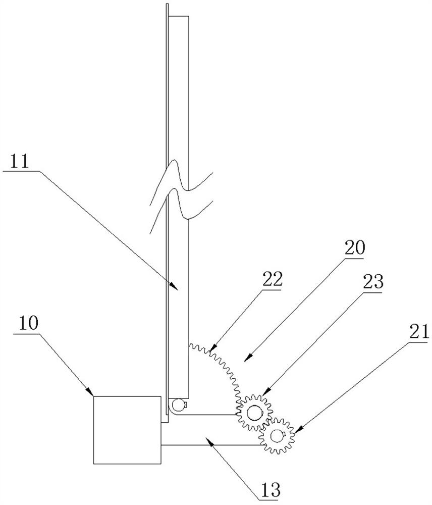
[0028] A hanging object hole cover plate with an electric flip structure, comprising an outer frame 10 arranged on the circumference of a rectangular hanging object hole matching the shape of the hanging object hole, the outer frame 10 includes two short sides opposite to each other and two opposite sides. The two long sides are arranged; the two short sides are respectively provided with the same structure of the openable guardrail 11; the two said long sides are respectively provided with the same structure of the movable and reversible door panel 12; the said guardrail One end of 11 is hinged with the support 13 arranged on the side wall of the short side; along the hinge of the guardrail 11 and the support 13 along the length direction of the guardrail 11, some opening and closing drive devices 20 for driv...


PUM


Abstract

The invention discloses a lifting hole cover plate of an electric turnover structure. The lifting hole cover plate comprises an outer frame, wherein the outer frame is arranged on the periphery of a rectangular lifting hole and is matched with the lifting hole in shape, and the outer frame comprises two opposite short edges and two opposite long edges; guardrails which are the same in structure and can be opened and closed are respectively arranged at the two short edges; movable and turnable door plates with the same structure are respectively arranged at the two long edges; one end of the guardrails is hinged to supports which are arranged on the side walls of the short edges; a plurality of opening and closing driving devices which are used for driving the guardrails to open and close are further arranged in the hinged positions of the guardrails and the supports in the length directions of the guardrails; sliding rails are further arranged on the side walls of the short edges in the length direction, and the sliding rails are located below the supports; and movable driving devices and turnable driving devices are respectively arranged in the middle of the two sides of the back faces of the door plates, and the movable driving devices are located below the turnable driving devices. The cover plate has the advantages of the reasonable structure and convenience in opening and closing, and the overall height is low after the door plates are opened.

Description

technical field [0001] The invention relates to the field of hanging object hole cover plates, in particular to an object hanging object hole cover plate with an electric flip structure. Background technique [0002] Due to the large size of some hanging object holes (for example: the length is usually 8 meters and the width is more than 3.2 meters); and the special requirements of the lifting operation or the door opening direction is limited, the door panel of the hanging object hole cannot adopt the conventional longitudinal short side folding technology , and when the horizontal split is adopted, due to the large span of the door plank, a larger type of steel beam is required to support the self-weight and external load of the door plank, and the conventional split door technology (the door plank and the outer frame are connected by hinges) has a high When it exceeds 1.6 meters, it will not only affect the hoisting sight, but also cause the hanging parts to be unable to ...

Claims


Application Information

Patent Timeline
Patent Type & Authority Applications(China)
IPC IPC(8): E06B5/01E06B3/50E06B9/04E05F15/603E05F15/614
CPCE06B5/01E06B3/5009E06B9/04E05F15/603E05F15/614E05Y2900/60
Inventor 马凤丹
Owner 江苏至善尚合电力科技有限公司
Why Eureka
Try Eureka