
Gearbox heat exchanger joint and heat exchanger

A technology of heat exchangers and gearboxes, applied in the field of heat exchange, can solve the problems of reducing work efficiency and increasing labor costs, and achieve the effects of effective use of space, enhanced durability, and enhanced thermal conductivity

Pending Publication Date: 2021-12-17
北京中煤汇嘉机电科技有限公司
View PDF0 Cites 0 Cited by
  • Summary
  • Abstract
  • Description
  • Claims
  • Application Information

AI Technical Summary

Problems solved by technology

[0004] When installing a traditional heat exchanger, two skilled workers are required to apply force to the joints of the heat exchanger on the inside and outside of the tube wall, so as to ensure that the heat exchanger will not break due to uneven force on both ends of the joint during installation. However, this will increase labor costs and reduce work efficiency

Method used


Image

  • Gearbox heat exchanger joint and heat exchanger
  • Gearbox heat exchanger joint and heat exchanger
  • Gearbox heat exchanger joint and heat exchanger

Examples


Embodiment Construction

[0046] Reference will now be made in detail to the exemplary embodiments, examples of which are illustrated in the accompanying drawings. When the following description refers to the accompanying drawings, the same numerals in different drawings refer to the same or similar elements unless otherwise indicated. The implementations described in the following exemplary examples do not represent all implementations consistent with the present invention. Rather, they are merely examples of apparatuses and methods consistent with aspects of the invention as recited in the appended claims.

[0047] The terminology used in the present invention is for the purpose of describing particular embodiments only and is not intended to limit the invention. As used herein and in the appended claims, the singular forms "a", "the", and "the" are intended to include the plural forms as well, unless the context clearly dictates otherwise. It should also be understood that the term "and / or" as use...


PUM


Abstract

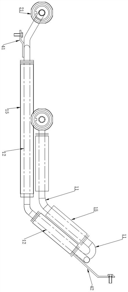
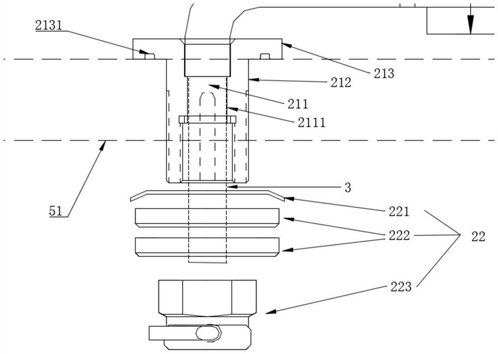
The invention relates to the technical field of heat exchange, and particularly relates to a gearbox heat exchanger joint and a heat exchanger. The gearbox heat exchanger joint comprises a first fixing part and a first mounting part, wherein the first fixing part is connected with the gearbox heat exchanger and a gearbox; a liquid inlet channel is formed in the first fixing part in the axial direction of the first fixing part; the first mounting part is connected with the first fixing part; and a limiting hole is formed in the inner wall of the liquid inlet channel and is used for limiting the first fixing part. The technical problem that the heat exchanger is broken due to uneven stress at the two ends of the joint during mounting is solved, and the technical effect of improving the mounting efficiency is achieved.

Description

Technical field: [0001] The invention relates to the technical field of heat exchange, in particular to a gearbox heat exchanger joint and a heat exchanger. Background technique: [0002] A heat exchanger is an energy-saving device that transfers heat between materials between two or more fluids at different temperatures. It transfers heat from a fluid with a higher temperature to a fluid with a lower temperature, so that the fluid temperature reaches the process The specified index is to meet the needs of process conditions, and it is also one of the main equipment to improve energy utilization. It is widely used in petroleum, chemical industry, metallurgy, electric power, shipbuilding, central heating, refrigeration and air conditioning. [0003] For example, in the gearbox of large equipment, lubricating oil is stored for lubrication, but the high temperature during equipment operation will reduce the performance of the lubricating oil, so a good lubrication and cooling s...

Claims


Application Information

Patent Timeline
Patent Type & Authority Applications(China)
IPC IPC(8): F16L19/02F16L19/03F16H57/04
CPCF16L19/0206F16L19/0212F16H57/0413F16H57/0417
Inventor 李占森李巍
Owner 北京中煤汇嘉机电科技有限公司
Learn More