Acoustic drainage structures and electronics

A technology of drainage structure and electronic equipment, applied in the field of acoustics, can solve the problems of low microphone loudness, hinder the sound conduction of waterproof membrane, affect the sound pickup quality of the microphone, etc., and achieve the effect of improving the sound pickup quality.

Active Publication Date: 2022-07-22
GEER TECH CO LTD
View PDF16 Cites 0 Cited by
  • Summary
  • Abstract
  • Description
  • Claims
  • Application Information

AI Technical Summary

Problems solved by technology

When smart wearable products are used in precipitation, swimming, showering and other scenarios, water will adhere to the surface of the waterproof membrane through the sound pickup hole. When collecting external sound, there are problems of low loudness and noise. Even if some water is thrown out by shaking the product, water will still remain on the waterproof membrane, which will still affect the sound pickup quality of the microphone.

Method used


Image

  • Acoustic drainage structures and electronics
  • Acoustic drainage structures and electronics
  • Acoustic drainage structures and electronics

Examples


no. 1 example

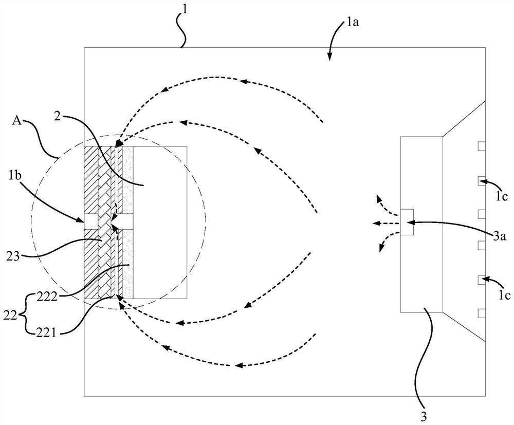
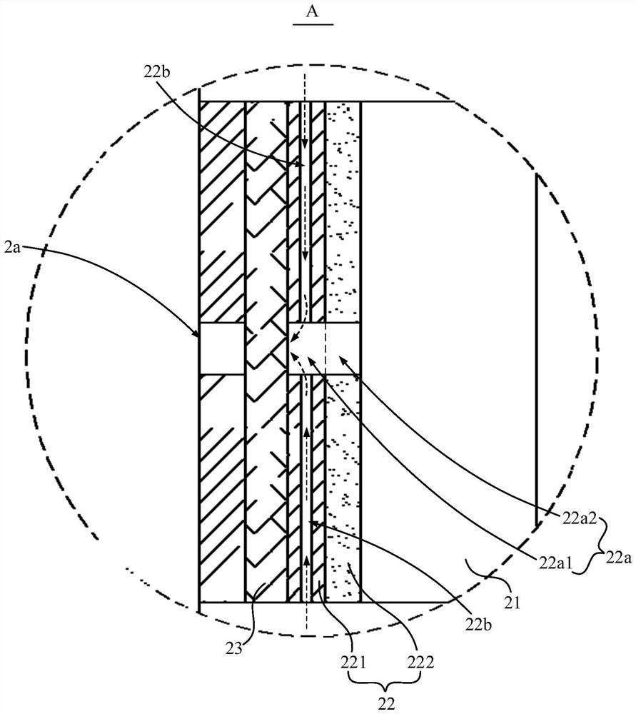
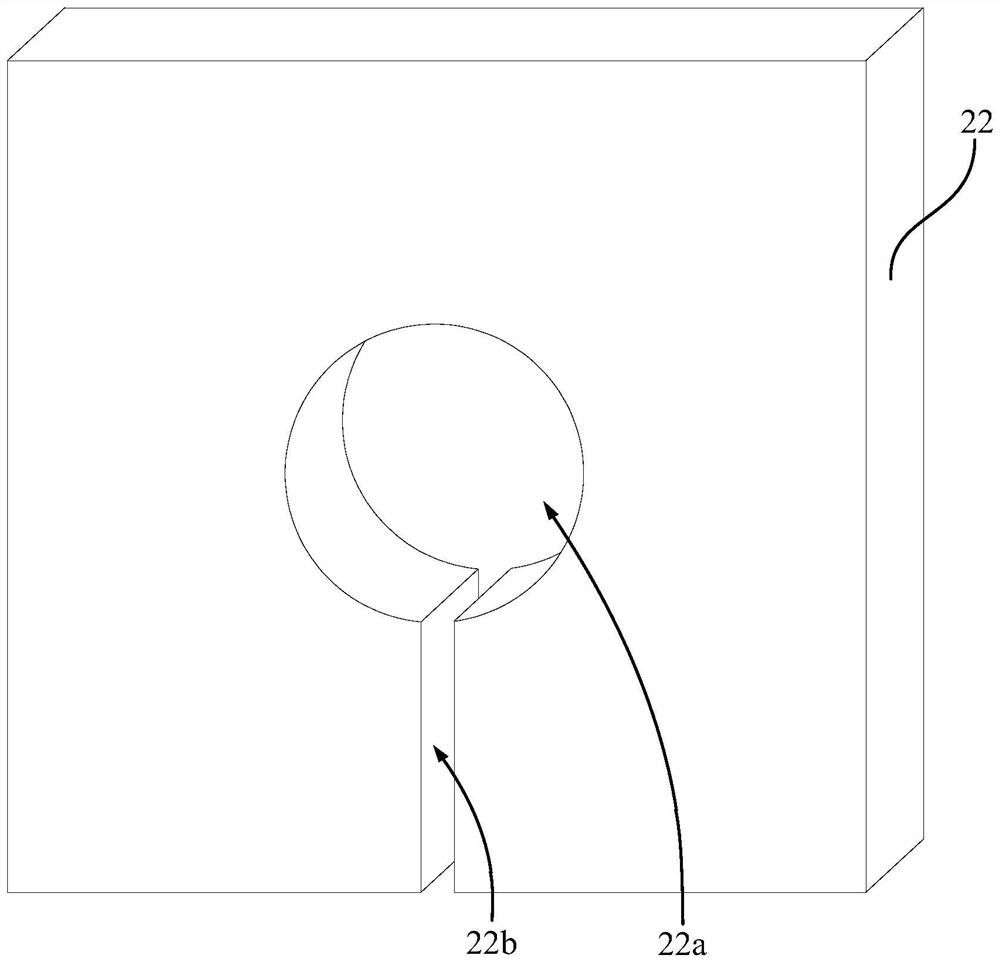
[0061] See 3, and combine figure 1 and figure 2 As shown, the air guide channel 22b passes through the outer wall of the connecting piece 22 and the hole wall of the second sound collecting hole 22a.

[0062] In this embodiment, the number of the air guide passages 22b is one, the air guide passage 22b is a single-channel structure connecting the pickup cavity 2a and the cavity 1a, and the shape of the air guide passage 22b includes, but is not limited to, a straight line, an arc shape , wave shape, at this time, the air vibration in the cavity 1a will cause the air vibration in the pickup cavity 2a through a single air guide channel 22b, and then drive the breathable waterproof membrane 23 to vibrate to realize the drainage of the breathable waterproof membrane 23. Because only one ventilation channel is opened on the connector 22, the processing procedure of the connector 22 can be reduced as much as possible on the premise of realizing the drainage function of the pickup ...

no. 2 example

[0064] see Figure 4 , and combine figure 1 and figure 2 As shown, the air guide passage 22b includes at least two air guide branches 22b1 provided on the connector 22, at least two air guide branches 22b1 are connected to each other, and at least one air guide branch 22b1 is connected to the pickup cavity 2a and the cavity 1a .

[0065] In this embodiment, the air guide channel 22b may include two or more air guide branches 22b1, wherein the two air guide branches 22b1 or the multiple air guide branches 22b1 are directly connected. For example, as Figure 4 As shown, the air guide channel 22b includes four air guide branches 22b1, and the four air guide branches 22b1 are arranged on the upper and lower sides of the second sound pickup hole 22a, and are located on two sides of the same side of the second sound pickup hole 22a. The air guide branches 22b1 communicate with each other, and the air guide branches 22b1 located on different sides of the second sound pickup hole...

no. 3 example

[0068] see Figure 5 , and combine figure 1 and figure 2 As shown, the air guide passage 22b further includes at least one communication branch 22b2, and each communication branch 22b2 communicates with two air guide branches 22b1.

[0069] In this embodiment, different from the solution of the second embodiment, some of the air guide branches 22b1 communicate with each other through the communication branch 22b2 instead of directly communicating with each other. The design that the air guide branches 22b1 are communicated through the communication branch 22b2 improves the air circulation between the air guide branches 22b1 and the air content in the air guide channel 22b, which is beneficial when the air in the air guide channel 22b vibrates. , the air in the second sound pickup hole 22a exerts a stronger driving force on the breathable waterproof membrane 23, drives the breathable waterproof membrane 23 to generate a larger vibration, and improves the shaking strength of ...


PUM


Abstract

The invention discloses an acoustic drainage structure and electronic equipment, wherein the acoustic drainage structure comprises a casing and an acoustic assembly, the casing is provided with a cavity and a first sound pickup hole communicated with the cavity; the acoustic assembly comprises a The pickup module and the sound-emitting unit, the pickup module includes a pickup unit, a connecting piece and a breathable waterproof membrane, the breathable waterproof membrane is arranged on the cavity wall of the cavity, the connecting piece connects the breathable waterproof membrane and the pickup unit, and the connecting piece is provided with a second The sound pickup hole, the breathable waterproof film covers the first sound pickup hole and the second sound pickup hole, the breathable waterproof film, the hole wall of the second sound pickup hole and the pickup unit form a sound pickup cavity; the connecting piece is provided with a connected pickup The cavity and the air guide channel of the cavity, so that the sound unit drives the breathable waterproof membrane to vibrate. The acoustic drainage structure proposed by the present invention can realize the drainage of the sound pickup module.

Description

technical field [0001] The invention relates to the technical field of acoustics, in particular to an acoustic waterproof structure and electronic equipment. Background technique [0002] At present, many smart wearable products have acoustic functions, such as smart watches, smart bracelets, etc. Smart wearable products generally have built-in microphones, which are used to collect user voices to implement corresponding voice interaction functions. [0003] In the related art, the pickup end cover of the microphone is provided with a waterproof membrane, and the waterproof membrane is located between the pickup hole of the product casing and the pickup end of the microphone, and is used for waterproof protection of the microphone. When the smart wearable product is used in precipitation, swimming, showering and other scenarios, water will adhere to the surface of the waterproof membrane through the sound pickup hole, and the accumulation of water on the waterproof membrane...

Claims


Application Information

Patent Timeline
Patent Type & Authority Patents(China)
IPC IPC(8): H04R1/08H04R1/44B08B7/02
CPCH04R1/086H04R1/44B08B7/026
Inventor 赵江涛
Owner GEER TECH CO LTD
Why Eureka
Try Eureka