A piezoelectric acoustic transducer with filtering function and its manufacturing method

An acoustic transducer and piezoelectric technology, applied in piezoelectric/electrostrictive transducer microphones, microphones, sensors, etc., can solve the problems of poor sound pickup effect and improve the sound pickup quality

Active Publication Date: 2022-06-17
武汉敏声新技术有限公司
View PDF9 Cites 0 Cited by
  • Summary
  • Abstract
  • Description
  • Claims
  • Application Information

AI Technical Summary

Problems solved by technology

[0004] The present invention solves the problem of poor sound pickup effect of piezoelectric MEMS microphones in the prior art by providing a piezoelectric acoustic transducer with filtering function and a manufacturing method thereof

Method used


Image

  • A piezoelectric acoustic transducer with filtering function and its manufacturing method
  • A piezoelectric acoustic transducer with filtering function and its manufacturing method
  • A piezoelectric acoustic transducer with filtering function and its manufacturing method

Examples


Embodiment 1

[0048] Embodiment 1 provides a piezoelectric acoustic transducer with filtering effect, see Figure 9 , the diaphragm 52 adopts a cantilever beam structure with a fixed center, and the center fixed end of the diaphragm 52 is established on the filter layer 56 .

[0049] The filter layer 56 includes a support column 57 , the support column 57 serves as a support for the diaphragm 52 , and the filter layer 56 defines the through hole 53 in a region outside the support column 57 . The diaphragm 52 can be divided into a plurality of diaphragms.

Embodiment 2

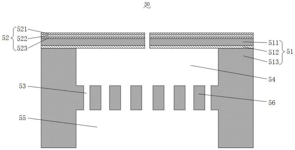
[0051] The diaphragm 52 adopts a cantilever beam structure with an outer periphery fixed, and the outer periphery fixed end of the diaphragm 52 is established on the substrate 51, such as image 3 shown. The diaphragm 52 can be divided into a plurality of diaphragms.

Embodiment 3

[0053] Embodiment 3 provides a method for manufacturing a piezoelectric acoustic transducer with filtering effect as described in Embodiment 1 or Embodiment 2, specifically a method for manufacturing a MEMS chip, including the following steps:

[0054] Step 1. Select a silicon wafer as the first insulating layer 513, and form a cavity structure on the silicon wafer through photolithography and etching processes;

[0055] Step 2, deposit silicon dioxide 541 in the cavity structure, and use chemical mechanical polishing process to grind the surface flat; see Figure 5 (corresponding to embodiment 2), Figure 11 (corresponding to embodiment 1);

[0056] Step 3, bonding a composite layer consisting of a transition layer 512 and a second insulating layer 511 on the silicon wafer with the cavity structure;

[0057] Step 4. Deposit materials in sequence on the composite layer to form a structural layer, and the structural layer is used as the diaphragm 52; see Image 6 (correspond...


PUM


Abstract

The invention belongs to the technical field of MEMS piezoelectric devices and semiconductor manufacturing, and discloses a piezoelectric acoustic transducer with filtering function and a manufacturing method thereof. Including the shell, the substrate and the MEMS chip; the shell and the substrate are enclosed to form a housing cavity, and the substrate is provided with a sound hole, which communicates with the housing cavity; the MEMS chip includes a substrate, a diaphragm and a filter layer; one end of the substrate is connected to the substrate Connection, the diaphragm is connected to the other end of the substrate away from the substrate, a back cavity is formed between the diaphragm and the substrate, the filter layer separates the back cavity into a top back cavity and a bottom back cavity, and the filter layer is provided with several through holes corresponding to Multiple cross-sectional areas of different sizes. The invention can effectively filter the clutter signal, so that the microphone has a good sound pickup effect.

Description

technical field [0001] The invention belongs to the technical field of MEMS piezoelectric device and semiconductor manufacturing, and more particularly, relates to a piezoelectric acoustic transducer with filtering function and a manufacturing method thereof. Background technique [0002] An acoustic transducer is an energy conversion device that can convert sound signals into electrical signals in different ways. A piezoelectric acoustic transducer is an energy conversion device that converts an acoustic signal into an electrical signal by using the piezoelectric effect. For example, a piezoelectric MEMS microphone is a typical piezoelectric acoustic transducer. In recent years, piezoelectric MEMS microphones have been widely used in smart wearable devices and smartphones due to their small size, stable performance, high signal-to-noise ratio, good sensitivity, and fast response speed. [0003] When the microphone picks up sound, it is inevitable that there will be useless...

Claims


Application Information

Patent Timeline
Patent Type & Authority Patents(China)
IPC IPC(8): H04R17/02H04R31/00
CPCH04R17/02H04R31/00H04R2201/003
Inventor 孙成亮杨超翔胡博豪林炳辉王雅馨
Owner 武汉敏声新技术有限公司
Why Eureka
Try Eureka