
Compression impeller assembling method and limiting tool thereof

An assembly method and impeller technology, applied in the field of mechanical processing, can solve problems such as installation difficulties, damaged parts, and installation failures, and achieve good installation effects

Pending Publication Date: 2021-12-21
CHONGQING JIANGJIN SHIPBUILDING IND
View PDF0 Cites 0 Cited by
  • Summary
  • Abstract
  • Description
  • Claims
  • Application Information

AI Technical Summary

Problems solved by technology

[0004] The purpose of the present invention is to provide a compressor impeller assembly method and its position-limiting tooling, aiming at solving the consequences of unreasonable process arrangement, difficult installation, improper installation or even damaged parts in the prior art during the hot assembly process. Technical issues that caused the installation to fail

Method used


Image

  • Compression impeller assembling method and limiting tool thereof
  • Compression impeller assembling method and limiting tool thereof
  • Compression impeller assembling method and limiting tool thereof

Examples


Embodiment Construction

[0051] Embodiments of the present invention are described in detail below, examples of which are shown in the drawings, wherein the same or similar reference numerals designate the same or similar elements or elements having the same or similar functions throughout. The embodiments described below by referring to the figures are exemplary and are intended to explain the present invention and should not be construed as limiting the present invention.

[0052]In describing the present invention, it should be understood that the terms "length", "width", "upper", "lower", "front", "rear", "left", "right", "vertical", The orientation or positional relationship indicated by "horizontal", "top", "bottom", "inner", "outer", etc. are based on the orientation or positional relationship shown in the drawings, and are only for the convenience of describing the present invention and simplifying the description, rather than Nothing indicating or implying that a referenced device or element ...


PUM


Abstract

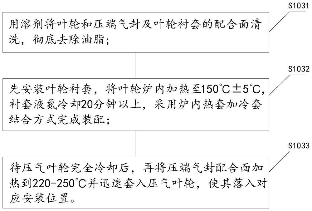
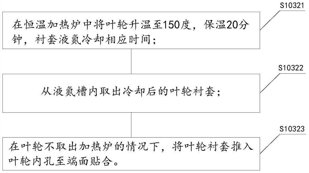
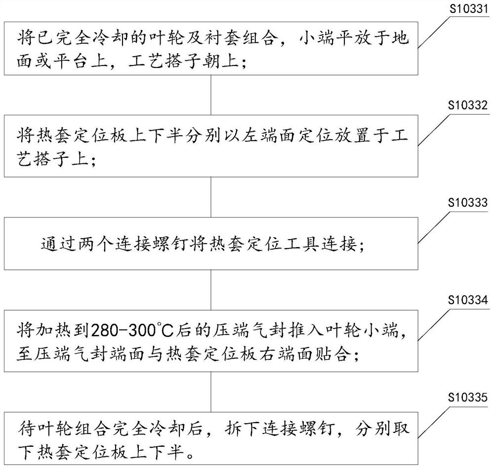
The invention relates to the technical field of machining, in particular to a compressor impeller assembling method and a limiting tool thereof. According to the theoretical basis, the structural characteristics of parts are combined, different fit interference magnitudes are set according to different materials, and a clear shrinkage fit specification is provided in the technical requirements of the parts; in the specification, different heating temperature ranges and shrinkage fit sequences are set for impellers made of different materials, and meanwhile, specific requirements are put forward for judging whether other treatment is carried out on an impeller lining or not; in the process setting process, the machining sequence of a back arc gas sealing face is adjusted, and allowance is reserved before shrinkage fit; the surface and the shrinkage fit limiting tool are used for fixing the assembly position of the air seal at the pressure end; and after shrinkage fit is completed, the air seal surface and other parts needing to be machined in a combination diagram are machined in place, so that the mounting effect of the compression impeller is better.

Description

technical field [0001] The invention relates to the field of mechanical processing, in particular to an assembly method of a compressor impeller and a position-limiting tool. Background technique [0002] At present, modern high-power medium-speed diesel engines are constantly advancing towards the development direction of increasing power density, improving energy consumption economy and reducing environmental emission pollution. The two models are respectively used to match the high-pressure ratio high-efficiency axial-flow turbocharger for propulsion and power station diesel engines. [0003] The compressed air impeller is made of 2618 (AlCuMgNi) and TC4 materials according to the different requirements of use. The pressure end air seal and the impeller bushing are made of 42CrMoA. The three parts adopt a large interference fit, and the technical requirements do not allow the use of Mechanical forces other than the weight of the parts are assembled. In the thermal assem...

Claims


Application Information

Patent Timeline
IPC IPC(8): B23P11/02B25B11/02
CPCB23P11/025B25B11/02
Inventor 杨雪琴王强何晓燕吴琳袁华罗攀闻俊飞张怡鲁建于
Owner CHONGQING JIANGJIN SHIPBUILDING IND
Learn More