
An anti-blocking steam trap with automatic displacement adjustment

An automatic adjustment and steam trap technology, applied in the direction of steam traps, mechanical equipment, etc., can solve the problems of steam flow adjustment, condensed water ingress, machine damage, etc., and achieve the effect of preventing condensation

Active Publication Date: 2022-02-11
艾肯(江苏)工业技术有限公司
View PDF0 Cites 0 Cited by
  • Summary
  • Abstract
  • Description
  • Claims
  • Application Information

AI Technical Summary

Problems solved by technology

[0004] In the prior art, the condensed water is generally simply discharged through the hydrophobic structure of the floating ball or buoy type, and the steam flow rate is not adjusted. Moreover, the steam that has already produced condensed water, although the steam is still in the gaseous state, it has already Near the condensation point, after passing through the steam trap, it is likely to only advance a short section of the pipeline to condense, and there will still be a certain amount of condensed water entering into the equipment using steam, causing certain damage to the machine

Method used


Image

  • An anti-blocking steam trap with automatic displacement adjustment
  • An anti-blocking steam trap with automatic displacement adjustment
  • An anti-blocking steam trap with automatic displacement adjustment

Examples


Embodiment Construction

[0035] The following will clearly and completely describe the technical solutions in the embodiments of the present invention with reference to the accompanying drawings in the embodiments of the present invention. Obviously, the described embodiments are only some, not all, embodiments of the present invention. Based on the embodiments of the present invention, all other embodiments obtained by persons of ordinary skill in the art without making creative efforts belong to the protection scope of the present invention.

[0036] see Figure 1-Figure 6 , the present invention provides technical solutions:

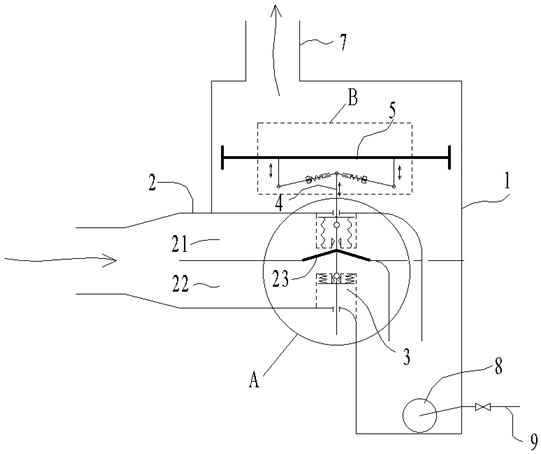
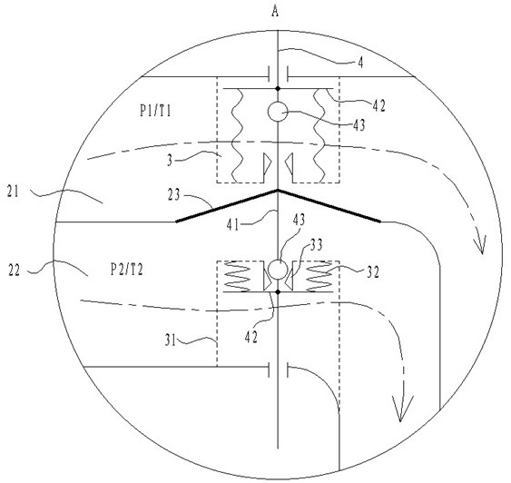
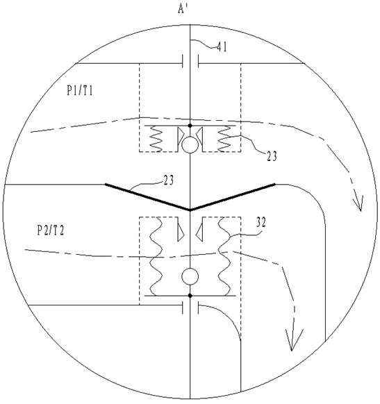
[0037] An anti-blocking steam trap with automatic displacement adjustment, comprising a housing 1, an inlet pipe 2, an oscillating assembly 3, a lifting assembly 4, an outlet pipe 7, and a discharge port 9, the lower side wall of the housing 1 is provided with an inlet pipe 2, and an inlet The part where the tube 2 is inserted into the housing 1 is divided into two paths by ...


PUM


Abstract

The invention relates to the technical field of steam traps, and specifically discloses an anti-blocking steam trap with automatic displacement adjustment, which includes a casing, an inlet pipe, an oscillating assembly, a lifting assembly, an outlet pipe, and a liquid discharge port. The part where the inlet pipe is inserted into the casing is divided into two paths by a partition, one is the first flow path and the other is the second flow path, a diaphragm is set on the partition, and the first flow path and the second flow path are respectively set on the side away from the diaphragm The vibration component, the lifting component includes a lifting rod, which is respectively connected to the diaphragm and two vibration components. Directional reciprocating jumping vibration. By dividing the inflow steam into the shell in two ways, one of the two ways of steam in the flow channel is decelerated and pressurized to condense to release more heat, and the other way of steam is decompressed to absorb heat and stay away from the condensation point.

Description

technical field [0001] The invention relates to the technical field of drain valves, in particular to an anti-blocking drain valve with automatic displacement adjustment. Background technique [0002] Steam traps are a commonly used component in industrial settings and are widely used in factories involving steam pipelines. [0003] The steam trap is a type of valve that discharges the condensed water during the steam transportation process and prevents the steam from being discharged. It is generally installed on the pipeline between the boiler and the steam-using device, and the water that condenses due to heat loss during the transportation pipeline Intercept and discharge to prevent condensed water from entering the subsequent heating position and causing adverse effects. [0004] In the prior art, the condensed water is generally simply discharged through the hydrophobic structure of the floating ball or buoy type, and the steam flow rate is not adjusted. Moreover, the...

Claims


Application Information

Patent Timeline
Patent Type & Authority Patents(China)
IPC IPC(8): F16T1/22F16T1/38
CPCF16T1/22F16T1/38
Inventor 郝刚张正凯刘梦祥
Owner 艾肯(江苏)工业技术有限公司
Learn More