
Method for monitoring deformation and stress state of support

A technology of stress state and support, applied in the direction of measuring devices, instruments, etc., to achieve simple construction technology, good durability, and solve the effect of deviation

Pending Publication Date: 2021-12-21
SHANGHAI RB RUBBER ISOLATOR TECH
View PDF0 Cites 0 Cited by
  • Summary
  • Abstract
  • Description
  • Claims
  • Application Information

AI Technical Summary

Problems solved by technology

[0003] The purpose of the present invention is to improve the deficiencies of the existing support, thereby providing a method for monitoring the deformation and stress state of the support, and solving the problem of multi-directional force monitoring of the support during service

Method used


Image

  • Method for monitoring deformation and stress state of support
  • Method for monitoring deformation and stress state of support
  • Method for monitoring deformation and stress state of support

Examples


Embodiment Construction

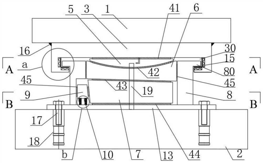
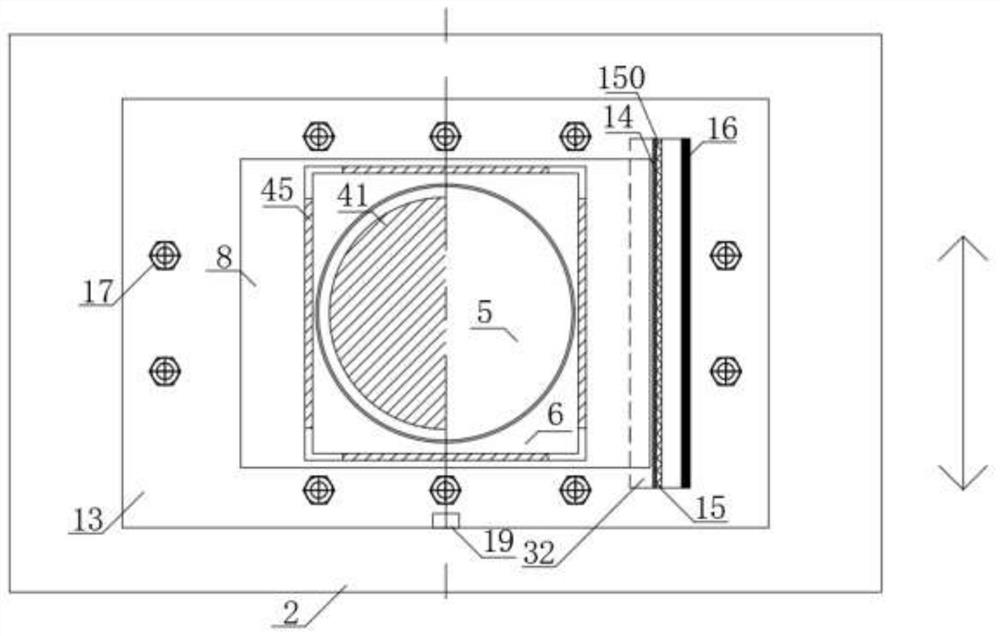
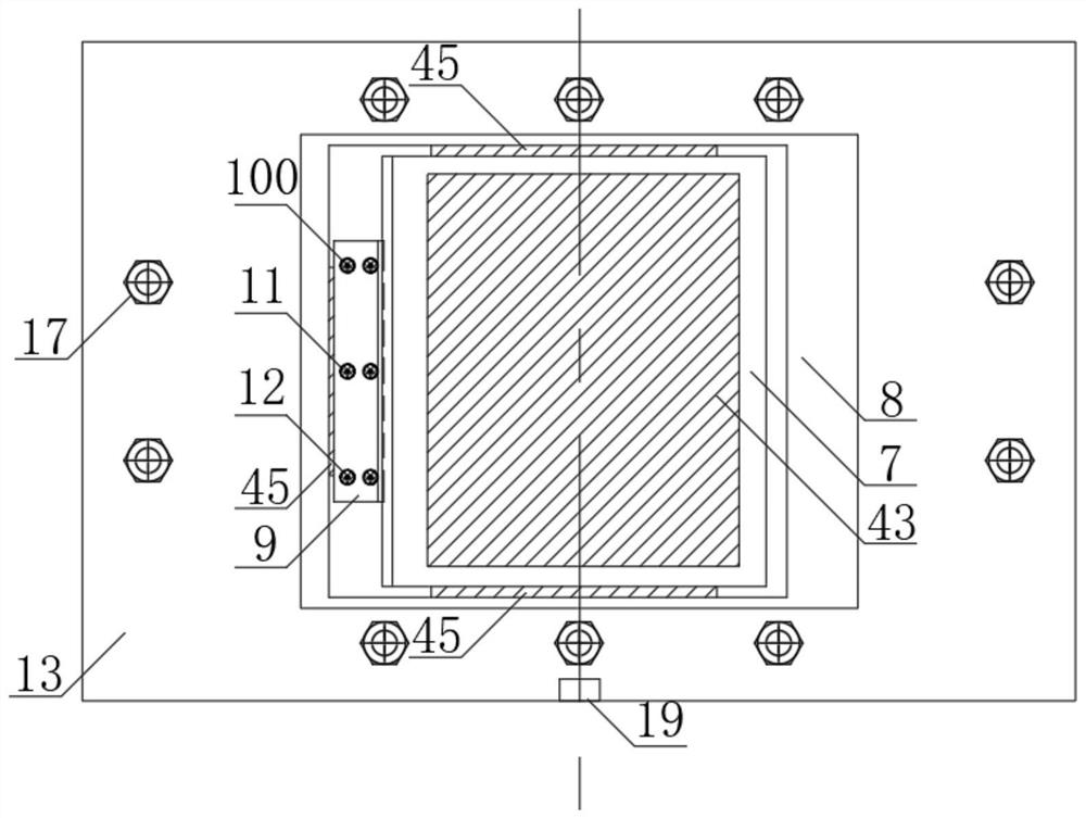
[0041] A method for monitoring the deformation and stress state of the support of the present invention will be described in further detail below in conjunction with the accompanying drawings. It should be understood that the following examples are only used to illustrate the present invention but not to limit the scope of the present invention. In the description of the embodiments of the present invention, orientation descriptions are involved, for example, orientations or positional relationships indicated by horizontal, vertical, oblique, inner, outer, left, right, front, rear, etc. are based on the orientations or positional relationships shown in the drawings. The positional relationship is only for the convenience of describing the present invention and simplifying the description, but does not indicate or imply that the referred device or element must have a specific orientation, be constructed and operated in a specific orientation, and thus should not be construed as ...


PUM


Abstract

The invention discloses a method for monitoring the deformation and stress state of a support. The method comprises the steps of determining the deformation coordination relation among a vertical moving wedge block, a horizontal moving wedge block and a force measurement wedge block of the support, obtaining the vertical pressure borne by the support and the corresponding deformation according to the deformation of a spring unit, determining the tensile force and the shear force borne by the support according to the deformation of a corrugated plate, and adjusting the force measurement precision by adjusting the rigidity parameter of an elastic unit. The deformation and stress state of the support in the service period can be observed in real time through the deformation of the elastic element according to the single-value monotone mapping relation between the deformation of the elastic element and the stress of the support, and the safety of the structure is improved.

Description

technical field [0001] The invention relates to the technical field of civil engineering bearings, in particular to a method for monitoring the deformation and stress state of the bearing. Background technique [0002] In civil engineering structures, especially in building structures and bridge structures, steel bearings are used for the fixed connection of the upper and lower members of the structure, and the joint moment release is realized through the spherical crown plate. Steel bearings can be divided into fixed bearings, one-way sliding bearings and two-way sliding bearings. As the key component of the boundary of the engineering structure, the health status of the bearing directly affects the safety, usability and comfort of the structure, and the health status of the bearing is closely related to its stress and deformation state. Real-time monitoring and evaluation is of great significance. At this stage, the methods used to measure the force of the bearing are ma...

Claims


Application Information

Patent Timeline
Patent Type & Authority Applications(China)
IPC IPC(8): G01D21/02
CPCG01D21/02
Inventor 欧阳郁汀施竹珺
Owner SHANGHAI RB RUBBER ISOLATOR TECH
Learn More