Generator rotor cooling structure and use method thereof

A technology of generator rotor and cooling structure, applied in the shape/pattern/structure of magnetic circuit, shape/pattern/structure of winding conductor, rotating parts of magnetic circuit, etc., can solve the complex manufacturing process of rotor coil and the heat transfer path of coil It can improve the overall cooling effect, the cooling effect is good, and the cost is low.

Inactive Publication Date: 2021-12-21
DONGFANG ELECTRIC MACHINERY +1
View PDF4 Cites 0 Cited by
  • Summary
  • Abstract
  • Description
  • Claims
  • Application Information

AI Technical Summary

Problems solved by technology

[0004] In order to overcome the deficiencies of the prior art, the present invention provides a generator rotor cooling structure and its use method, which solves the existing problems in the prior art, such as complex manufacturing process of the rotor coil, high cost, long coil heat transfer path, and easy occurrence of rotor coils. Problems such as high temperature rise of the coil at the bottom of the body

Method used


Image

  • Generator rotor cooling structure and use method thereof
  • Generator rotor cooling structure and use method thereof
  • Generator rotor cooling structure and use method thereof

Examples


Embodiment 1

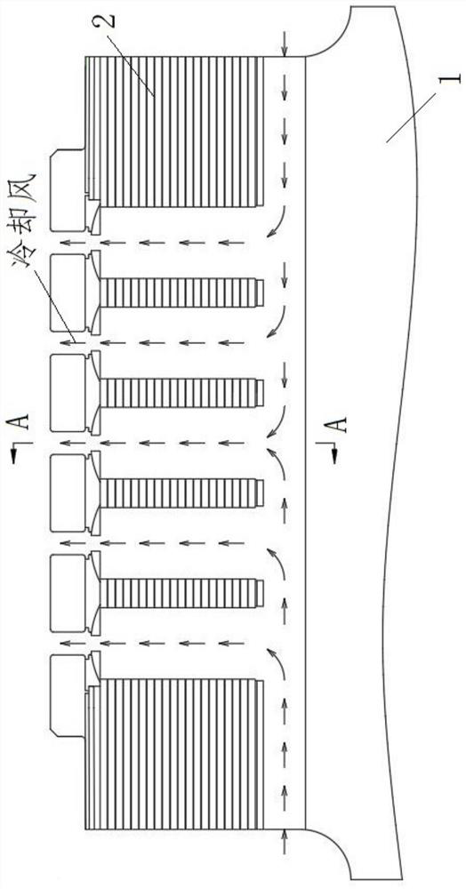
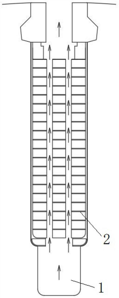
[0056] Such as Figure 1 to Figure 6 As shown, a generator rotor cooling structure includes a rotor body 1 and a rotor coil 2 wound on the outer surface of the rotor body 1. The end surface of the rotor body 1 is provided with a first slot 3 extending to the opposite end surface. , the side of the rotor body 1 is provided with a second slot 4 intersecting with the first slot 3 .

[0057] When the generator rotates, the cooling air enters from the first slot 3 on the end surface of the rotor body 1 and is discharged from the second slot 4 on the side of the rotor body 1 .

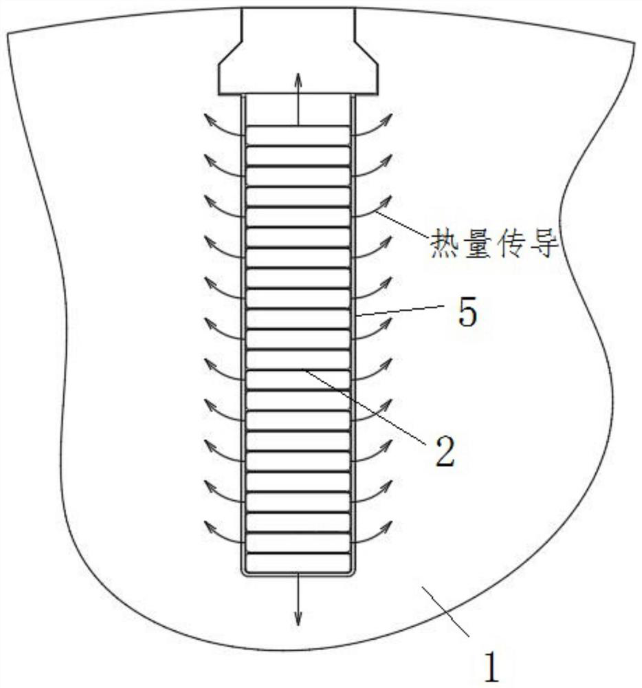
[0058] The invention combines the advantages of traditional internal cooling and external cooling. The lower coil of the rotor body 1 is directly cooled by the cooling air, and the cooling effect is better. The end face of the rotor body 1 and the side surface of the rotor body 1 are provided with a first slot 3 and a second slot 4 respectively, and the structure of the rotor coil 2 is exactly the same as t...

Embodiment 2

[0071] Such as Figure 1 to Figure 6 As shown, as a further optimization of Embodiment 1, this embodiment includes all the technical features of Embodiment 1. In addition, this embodiment also includes the following technical features:

[0072] As a preferred technical solution, the cavity of the first slot 3 extends to the axis of the rotor body 1 .

[0073] This makes the ventilation area of ​​the first slot 3 larger, and also makes the ventilation depth of the rotor body 1 larger, further improving the ventilation volume and cooling effect.

[0074] As a preferred technical solution, the size of one end of the first slot 3 close to the center of the end surface of the rotor body 1 is smaller than the size of the end close to the edge of the rotor body 1 .

[0075] This makes the ventilation area near the end of the rotor coil 2 larger, which is more conducive to the heat dissipation of the rotor coil 2 .

[0076] As a preferred technical solution, it is characterized in t...

Embodiment 3

[0081] A method for using a generator rotor cooling structure according to the present invention includes the following steps:

[0082] S1, start the engine to rotate the generator;

[0083] S2 , the cooling air enters from the first slot 3 on the end surface of the rotor body 1 , and the cooling air is discharged from the second slot 4 on the side of the rotor body 1 .

[0084] When the generator rotates, the cooling air enters from the first slot 3 on the end surface of the rotor body 1 and is discharged from the second slot 4 on the side of the rotor body 1 .

[0085] The invention combines the advantages of traditional internal cooling and external cooling. The lower coil of the rotor body 1 is directly cooled by the cooling air, and the cooling effect is better. The end face of the rotor body 1 and the side surface of the rotor body 1 are provided with a first slot 3 and a second slot 4 respectively, and the structure of the rotor coil 2 is exactly the same as that of th...


PUM


Abstract

The invention discloses a generator rotor cooling structure and a use method thereof.The generator rotor cooling structure comprises a rotor body and a rotor coil wound around the outer surface of the rotor body; the end face of the rotor body is provided with a first channel extending towards the other opposite end face; and the side surface of the rotor body is provided with a second channel intersecting with the first channel. The problems that in the prior art, a rotor coil is complex in manufacturing process, high in cost and long in coil heat transfer path, and temperature rise of a coil at the bottom of a rotor body is high easily occur are solved.

Description

technical field [0001] The invention relates to the technical field of generator cooling, in particular to a generator rotor cooling structure and an application method thereof. Background technique [0002] At present, the cooling methods of the rotor coil of the turbogenerator are divided into two methods: internal cooling and external cooling. In the internal cooling method, the heat of the coil is directly taken away by the cold air, and the cooling effect is better, but this cooling method needs to open multiple cooling holes on the coil, the coil manufacturing process is complicated, and the cost is high. figure 1 It is a typical internally cooled rotor coil air path. [0003] For externally cooled rotor coils, there are no holes or slots on the rotor coils. The heat of the rotor coils is first transferred to the insulating material 5 in the coil slots, and then transferred to the rotor body by the insulating materials 5, and finally passes through the rotor coils. T...

Claims


Application Information

Patent Timeline
Patent Type & Authority Applications(China)
IPC IPC(8): H02K1/32H02K3/24
CPCH02K1/32H02K3/24
Inventor 李积霞蒲太平彭礼明杨正锋李斌郭弘凌曹志伟王继豪
Owner DONGFANG ELECTRIC MACHINERY
Why Eureka
Try Eureka