Radial floating type high-heat-dissipation motor

A high heat dissipation, floating technology, applied in the direction of electric components, electromechanical devices, casings/covers/supports, etc., can solve the problems of inconvenient structure use, motor burnout and scrap, poor heat dissipation effect, etc., to avoid bumps , The effect of reducing load energy consumption and narrowing the range

Active Publication Date: 2021-12-21
东台领裕智能科技有限公司
View PDF5 Cites 4 Cited by
  • Summary
  • Abstract
  • Description
  • Claims
  • Application Information

AI Technical Summary

Problems solved by technology

[0002] The motor is an electric motor or an engine. The working principle is that the rotor of the starter is driven to rotate by the energized coil in the magnetic field, and the small gear on the rotor drives the flywheel of the engine to rotate. The motor casing is an important part of the motor. The existing motor casing The heat dissipation is simply relying on heat sinks or heat dissipation strips for heat dissipation, resulting in poor heat dissipation. Once the heat dissipation of the motor is not good, the local heat will be too high, which may lead to the risk of motor burnout and scrapping. Therefore, the heat dissipation structure of the motor is more critical. For this reason, some existing technologies use a fan installed on the rear end of the motor to dissipate heat, but the heat dissipation is uneven and the effect is poor, and the fan protrudes outside the rear end of the motor, which will cause bumps during transportation and installation, or It will be very inconvenient to use the structure when running at low speed without heat dissipation

Method used


Image

  • Radial floating type high-heat-dissipation motor
  • Radial floating type high-heat-dissipation motor
  • Radial floating type high-heat-dissipation motor

Examples


Embodiment Construction

[0020] The content of the present invention will be further described in detail below in conjunction with the accompanying drawings.

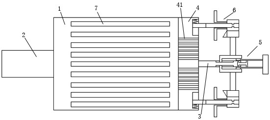
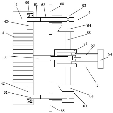
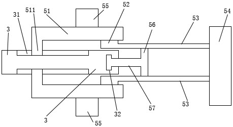
[0021] Such as Figures 1 to 4 As shown, a radial floating high heat dissipation motor includes a motor housing 1, a front end of the rotating shaft 2, a rear end of the rotating shaft 3, a floating cooling mechanism 6, a rear connecting cover 4, a cooling strip 6, and an axial drive mechanism 5. The front end part 2 of the rotating shaft is installed in the middle of the front end of the motor housing 1; the rear end part 3 of the rotating shaft is installed in the middle of the rear end of the motor housing 1; the middle of the rear end connection cover 4 is evenly provided with a plurality of ventilation Slot 41; the rear end of the motor housing 1 is equipped with a rear connection cover 4; a plurality of cooling strips 6 are evenly installed on the outside of the motor housing 1; the floating heat dissipation mechanism 6 includes a floatin...


PUM


Abstract

The invention discloses a radial floating type high-heat-dissipation motor which comprises a motor shell, a rotating shaft front end part, a rotating shaft rear end part, a floating heat dissipation mechanism, a rear end connecting cover, heat dissipation strips and an axial driving mechanism. A plurality of driven ring body gears are uniformly mounted on the periphery of the outer side of the rear end connecting cover, and a plurality of air inducing blades are uniformly mounted on the periphery of the inner end of each driven ring body gear so that a structure that the plurality of air inducing blades are uniformly arranged on the periphery of the rear end of the motor shell for rotary air inducing and heat dissipation is formed; and through conduction through a ventilation slot, the inner side and the outer side of the motor shell achieve synchronous heat dissipation, and the heat dissipation uniformity and efficiency are improved.

Description

technical field [0001] The invention relates to a radial floating motor with high heat dissipation. Background technique [0002] The motor is an electric motor or an engine. The working principle is that the rotor of the starter is driven to rotate by the energized coil in the magnetic field, and the small gear on the rotor drives the flywheel of the engine to rotate. The motor casing is an important part of the motor. The existing motor casing The heat dissipation is simply relying on heat sinks or heat dissipation strips for heat dissipation, resulting in poor heat dissipation. Once the heat dissipation of the motor is not good, the local heat will be too high, which may lead to the risk of motor burnout and scrapping. Therefore, the heat dissipation structure of the motor is more critical. For this reason, some existing technologies use a fan installed on the rear end of the motor to dissipate heat, but the heat dissipation is uneven and the effect is poor, and the fan p...

Claims


Application Information

Patent Timeline
Patent Type & Authority Applications(China)
IPC IPC(8): H02K5/20H02K5/18H02K9/06
CPCH02K5/207H02K5/18H02K9/06Y02E60/16
Inventor 曾芳勤
Owner 东台领裕智能科技有限公司
Why Eureka
Try Eureka