Speed protection controller for belt type oil pumping unit

A technology for protecting controllers and pumping units, which is applied in the fields of mining fluids, cooling/ventilation/heating transformation, electrical components, etc. It can solve problems such as synchronous heat dissipation, PLC controller damage, inconvenient maintenance of electrical components, etc., to achieve improved support Strength, the effect of reducing the contact area

Pending Publication Date: 2020-03-31
张海涛
View PDF0 Cites 0 Cited by
  • Summary
  • Abstract
  • Description
  • Claims
  • Application Information

AI Technical Summary

Problems solved by technology

[0004] The purpose of the present invention is to provide a speed protection controller for belt pumping units, which can effectively solve the problem that the existing speed protection controllers for belt pumping units are not convenient enough to install heat dissipation structures , the heat dissipation structure cannot realize synchronous heat dissipation up and down; when the existing speed protection controller for the belt pumping unit is installed on the PLC controller, the PLC controller cannot be well protected, and the PLC controller The shock absorption effect is average, and the PLC controller is prone to damage; the existing speed protection controller for the belt pumping unit cannot better partition the electrical components when installing the electrical components Installation; the existing speed protection controller used for belt pumping units is inconvenient to maintain the electrical components

Method used


Image

  • Speed protection controller for belt type oil pumping unit
  • Speed protection controller for belt type oil pumping unit
  • Speed protection controller for belt type oil pumping unit

Examples


Embodiment Construction

[0038] The technical solutions of the present invention will be clearly and completely described below in conjunction with the embodiments. Apparently, the described embodiments are only some of the embodiments of the present invention, not all of them. Based on the embodiments of the present invention, all other embodiments obtained by persons of ordinary skill in the art without creative efforts fall within the protection scope of the present invention.

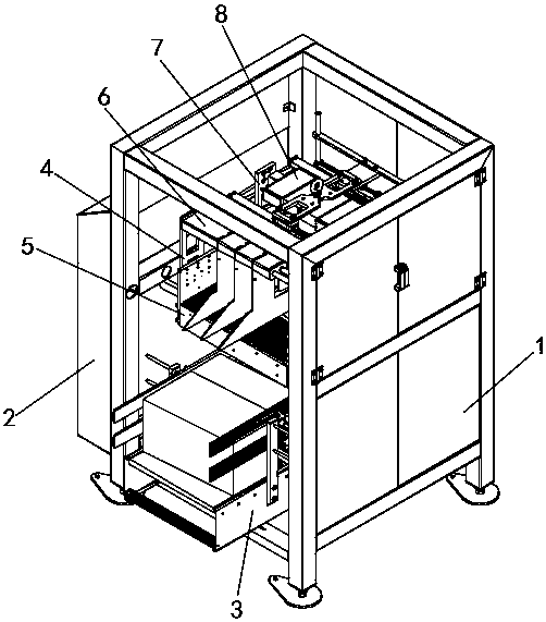
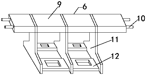
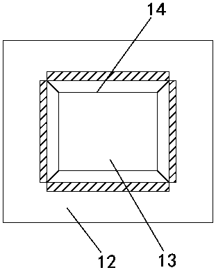
[0039] see Figure 1-8 As shown, a speed protection controller for a belt pumping unit includes a mounting frame 1, a reduction box 2 is installed on the side of the mounting frame 1, and an electrical fixing frame 3 is installed at the inner bottom of the mounting frame 1. The middle part of the inner side of the mounting frame 1 is equipped with a clamping frame 4, and the inner side of the clamping frame 4 is equipped with a circuit box 5 and a heat dissipation member 6. box 7, and the inside of the installation box 7 i...


PUM


Abstract

The invention discloses a speed protection controller for a belt type oil pumping unit. The speed protection controller comprises a mounting frame, wherein a reduction gearbox is mounted on the side edge of the mounting frame; an electric appliance fixing frame is mounted at the bottom end of the interior of the mounting frame; a clamping frame is mounted in the middle of the inner side of the mounting frame; a circuit box and a heat dissipation component are mounted on the inner side of the clamping frame; the heat dissipation component is positioned above the circuit box; a mounting box is mounted at the position, close to the top, of the inner side of the mounting frame; a PLC is arranged on the inner side of the mounting box; the heat dissipation component comprises a plurality of setsof transversely-arranged clamping blocks; a clamping plate is arranged between every two adjacent clamping blocks; and inserting rods are arranged on the side walls penetrating through the clamping blocks and the clamping plates. According to the speed protection controller, the PLC can be effectively protected, the PLC is prevented from being damaged during use, and a velometer, a frequency converter, a driving power supply and an overload switch are convenient to mount and maintain; and meanwhile, a good heat dissipation effect is achieved, and the controller is prevented from being influenced by high temperature.

Description

technical field [0001] The invention relates to the field of controllers, in particular to a speed protection controller for a belt pumping unit. Background technique [0002] The belt pumping unit drives the belt through the motor to drive the relevant structure of the pumping unit to achieve the pumping speed. The speed of the motor determines the speed of the pumping unit. In order to avoid excessive To work, it is necessary to use the speed protection controller to control the speed of the motor, so that the speed of the motor is in the normal operating range, so as to realize the protection of the pumping unit. [0003] There are certain disadvantages in the existing speed protection controller for belt pumping units in use. The existing speed protection controller for belt pumping units is not convenient enough to install the heat dissipation structure, and the heat dissipation structure cannot Realize synchronous heat dissipation from top to bottom; when the existing...

Claims


Application Information

Patent Timeline
Patent Type & Authority Applications(China)
IPC IPC(8): E21B43/12H05K7/20
CPCE21B43/121H05K7/20172
Inventor 张海涛张晨吴涛张延辉米世超祁晨龙石磊曹洋赵培杰庄飞
Owner 张海涛
Why Eureka
Try Eureka