Fiber bundle with pieced part, process for producing same, and process for producing carbon fiber

Inactive Publication Date: 2011-09-08
TORAY IND INC
View PDF1 Cites 13 Cited by
  • Summary
  • Abstract
  • Description
  • Claims
  • Application Information

AI Technical Summary

Benefits of technology

[0034]When subjected to continuous calcination in a calcination step, the fiber-joint-portion-containing fiber bundle according to an embodiment of the invention does not suffer breakage of fiber bundles or slippage of fibers of the fiber bundles out of the fiber bundles during the calcination step, serving to prevent heat accumulation in the fiber joint portion and efficiently achieve heat removal from the fiber joint portion.
[0035]Consequently, the fiber-joint-portion-containing fiber bundle according to an embodiment of the invention can be passed conti

Problems solved by technology

However, though it is actually possible to join the end portions of precursor fiber bundles by this method, the fiber density will be too high in the fiber joint portion formed, giving rise to the problem of runaway of the oxidization reaction caused during the oxidizing step by the heat generated from the precursor fiber bundles themselves.
Accordingly, there have been accidents involving thermal destruction and burnout of the fiber joint portion.
If the temperature of the oxidizing step is lowered significantly, however, a longer time will be required for carrying out the oxidizing step, leading to a considerable decrease in the productivity for the desired carbon fibers.
In addition, sufficient interlacement will not be achieved in the fiber joint portion, leading to a smaller binding strength between the precursor fiber bundles.
As a result, the fiber bundles will become unable to resist the tension caused during the process, leading to rupture or slippage of the bundles in the fiber joint portion.
Though this method can reduce the quantity of heat accumulation, however, the heat in the joint portion cannot be removed sufficiently, and breakage of the yarn may still occur easily in the joint portion where the fiber density has increased.
In addition, the ox

Method used


Image

  • Fiber bundle with pieced part, process for producing same, and process for producing carbon fiber
  • Fiber bundle with pieced part, process for producing same, and process for producing carbon fiber
  • Fiber bundle with pieced part, process for producing same, and process for producing carbon fiber

Examples


example 1

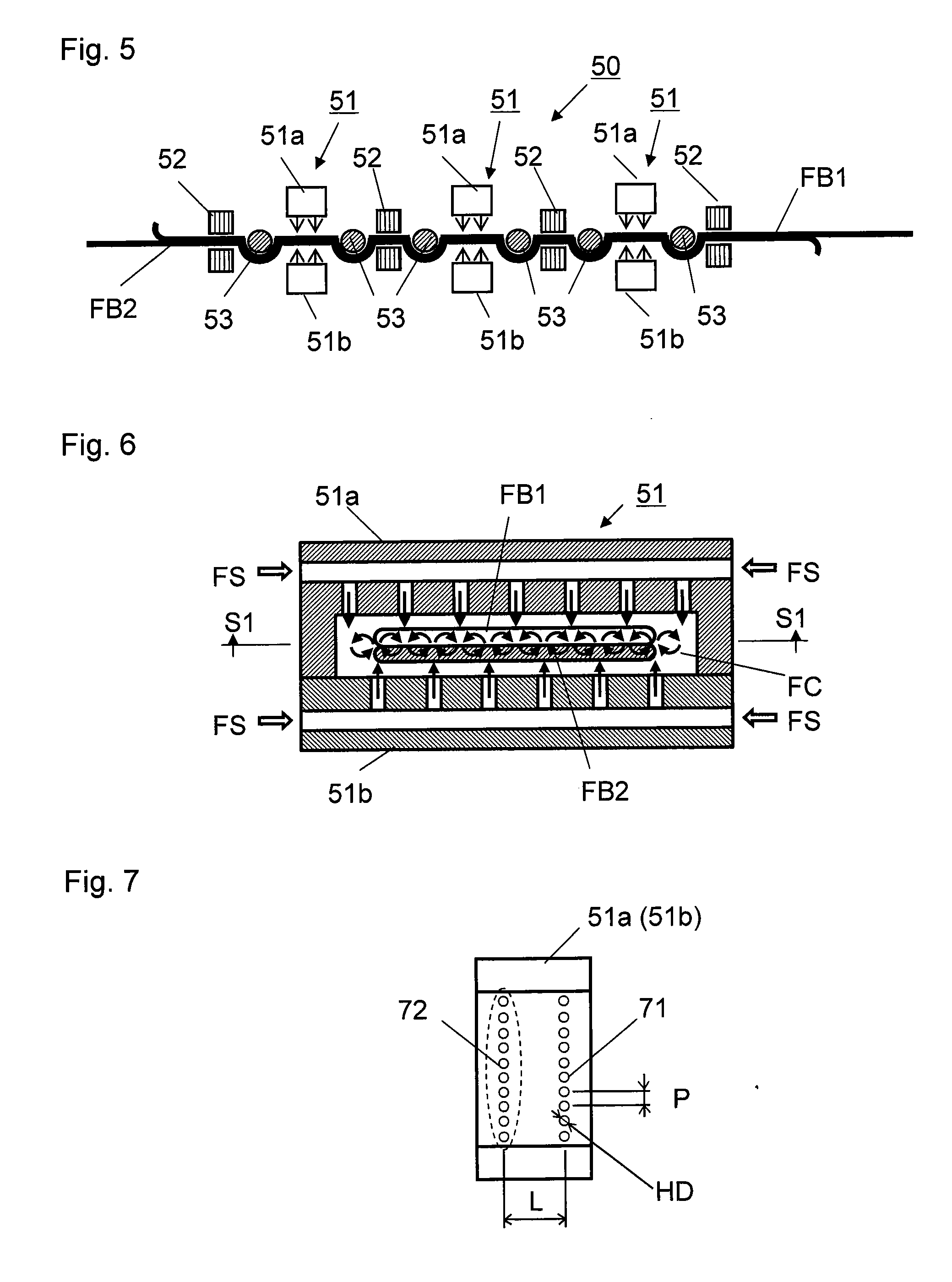
[0143]An end portion 5 of a first precursor fiber bundle FB1 and an end portion 6 of a second precursor fiber bundle FB2 were superposed over a length of 400 mm as the size of a superposed fiber bundle portion. The fiber bundle joining apparatus shown in FIG. 5 was used to join the two fiber bundles by forming the superposed fiber bundle portion. Three fiber interlacing devices 51 were used to perform this. In each fiber interlacing device 51, the fluid jetting holes in the first fluid jetting hole series 71 and the second fluid jetting hole series 72 had a diameter of 1.5 mm, and the spacing between the fluid jetting holes was 2.5 mm. The distance (hole series spacing) L between the two fluid jetting hole series 71 and 72 was 30 mm as measured in the length direction of the fiber bundles. The superposed first and second fiber bundles FB1 and FB2 were relaxed by 9.0% in the fiber bundle relaxing device 53 using a round bar.

[0144]Subsequently, air jets compressed at a pressure of 0.4...

example 2

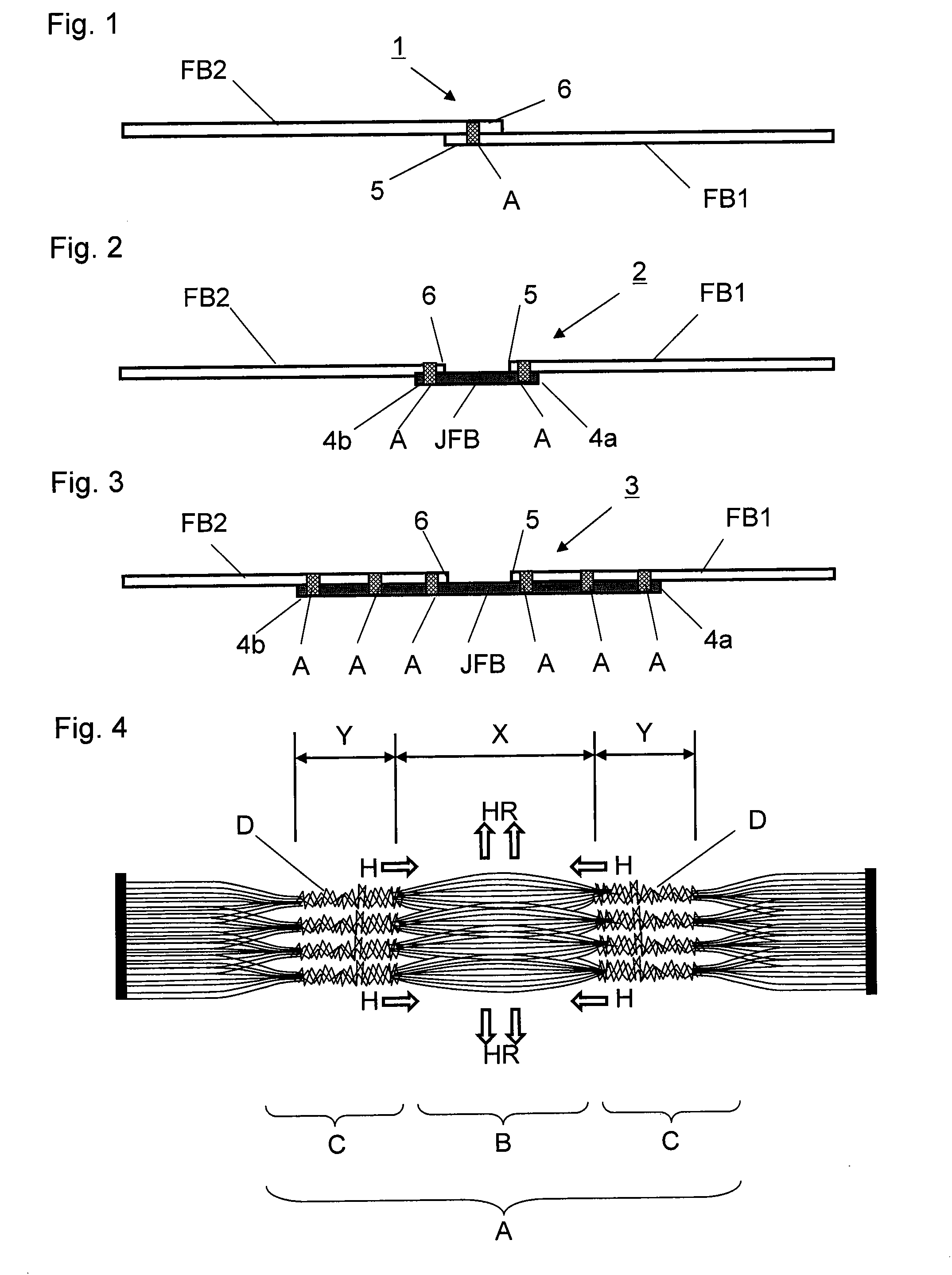
[0147]The same first precursor fiber bundle FB1 and second precursor fiber bundle FB2 as in Example 1 were prepared. Elsewhere, a joint fiber bundle JFB was prepared from a carbon fiber bundle that comprised 24,000 filaments and had a heat conductivity of 55 W / m·K. The three fiber bundles prepared were superposed in a state as shown in FIG. 3. Both the superposed portion of the first precursor fiber bundle FB1 and the carbon fiber bundle JFB, and the superposed portion of the second precursor fiber bundle FB1 and the carbon fiber bundle JFB, had a length of 400 mm. The distance between the end of the first precursor fiber bundle FB1 and the end of the second precursor fiber bundle FB2 was 500 mm.

[0148]The fiber bundle joining apparatus shown in FIG. 5 was used to join the first precursor fiber bundle FB1 and the carbon fiber bundle JFB and join the second precursor fiber bundle FB1 and the carbon fiber bundle JFB in the superposed fiber bundle portion. Here, the same three fiber int...

example 3

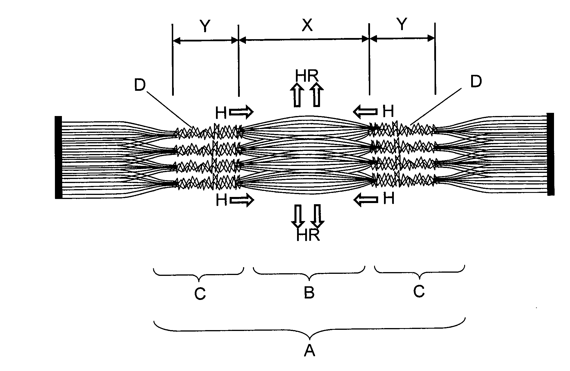
[0157]An end portion of a first precursor fiber bundle FB1 and an end portion of a second precursor fiber bundle FB2, opposed to each other with a spacing, were bridged and joined by a joint fiber bundle JFB, which was a carbon fiber bundle comprising 48,000, 24,000, or 12,000 filaments to prepare three fiber-joint-portion-containing fiber bundle samples. In joining the superposed fiber bundles, the fiber bundles were superposed first, and relaxed by 9.0% in their length direction, and subsequently three fiber interlacing devices 51 were used to join the fiber bundles in the superposed portion. Each fiber interlacing device 51 had a first fluid jetting hole series 71 and a second fluid jetting hole series 72. From the fluid jetting holes located at intervals to form each fluid jetting hole series, air jets compressed at a pressure of 0.4 MPa were emitted for two seconds to interlace the multiple fibers in each fiber bundle in the superposed portion. This produced a fiber-joint-porti...


PUM

PropertyMeasurementUnit
Lengthaaaaaaaaaa
Lengthaaaaaaaaaa
Lengthaaaaaaaaaa

Abstract

A fiber bundle which has a pieced part formed by jetting a pressurized fluid against a fiber-bundle overlap is formed either by directly superposing the ending part of a fiber bundle composed of many fibers on the beginning part of another fiber bundle composed of many fibers or by superposing the end part and the beginning part on a jointing fiber bundle composed of many fibers, whereby the many fibers of the fiber bundles are interlaced with one another to thereby piece up the fiber bundles. The pieced part comprises an opened-fiber part in which the fibers have been opened and interlaced-fiber parts respectively located on both sides thereof, each interlaced-fiber part being composed of a plurality of constituent interlaced parts located apart in the width direction for the fiber bundle.

Description

FIELD OF THE INVENTION[0001]The invention relates to a fiber bundle having a fiber joint portion, a production method thereof, and a carbon fiber production method. When carbon fiber is produced from precursor fiber bundles designed for carbon fiber produce, it is sometimes necessary to continue supplying such precursor fiber bundles to a carbon fiber production process for a long period of time. In such cases, it is necessary to join the tail end portion of a precursor fiber bundle for carbon fiber production with the front end portion of another precursor fiber bundle for carbon fiber production to produce a continuous precursor fiber bundle. A fiber-joint-portion-containing fiber bundle according to the invention can be used effectively for such production of a continuous precursor fiber bundle.BACKGROUND OF THE INVENTION[0002]In general, precursor fiber bundles specially designed for carbon fiber production are used in carbon fiber production processes. These precursor fiber bun...

Claims


Application Information

Patent Timeline
IPC IPC(8): D01F9/12D02G3/02D02G3/22D01H13/30
CPCB65H69/06B65H2701/314B65H2701/38Y10T428/2918D02J1/08Y10T428/2913Y10T428/298D01F9/22B65H69/00D01F6/18
Inventor MISHIMA, KUNIHIROHIROSE, TAKAMITSUKATO, KIMIYASUOZAKI, MITSUTOSHIWATANABE, DAIKI
Owner TORAY IND INC
Why Eureka
Try Eureka