
O-shaped leg corrector

An orthotic and over-correction technology, which is applied in medical science, non-surgical orthopedic surgery, etc., can solve problems such as poor comfort, unsatisfactory use effect, and influence on patients' daily life, and achieve easy wearing, good application value, and strong correction Effect

Pending Publication Date: 2021-12-24
赵鹏
View PDF0 Cites 0 Cited by
  • Summary
  • Abstract
  • Description
  • Claims
  • Application Information

AI Technical Summary

Problems solved by technology

At present, the corrective braces on the market usually use the time of sleep at night, and are forcibly bound with cloth bandages for correction. This kind of corrective device has limitations in time and space, and poor comfort, which greatly affects the daily life of patients. The effect of time use is not ideal. Therefore, designing an O-shaped leg correction device that can be worn daily to ensure certain normal activities and has a good correction effect has become the direction of further improvement.

Method used


Image

  • O-shaped leg corrector
  • O-shaped leg corrector
  • O-shaped leg corrector

Examples


Embodiment 1

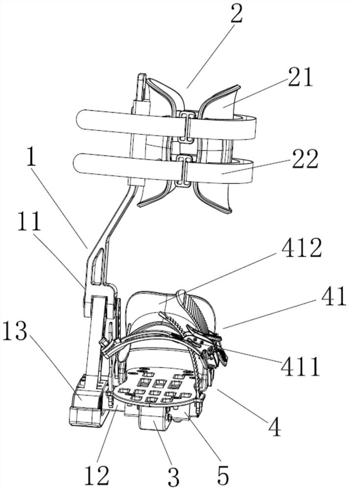
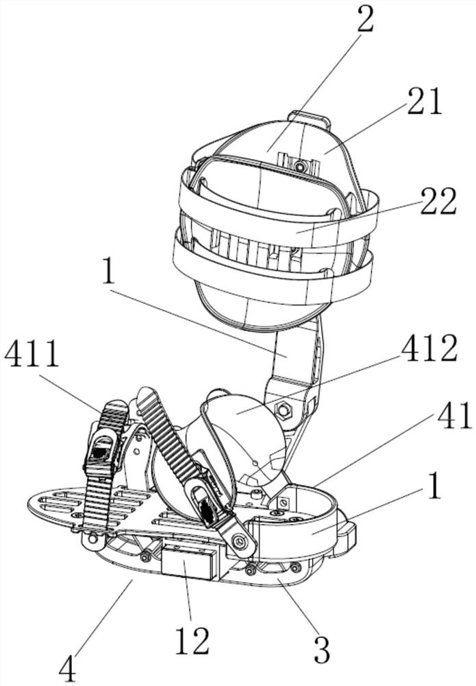
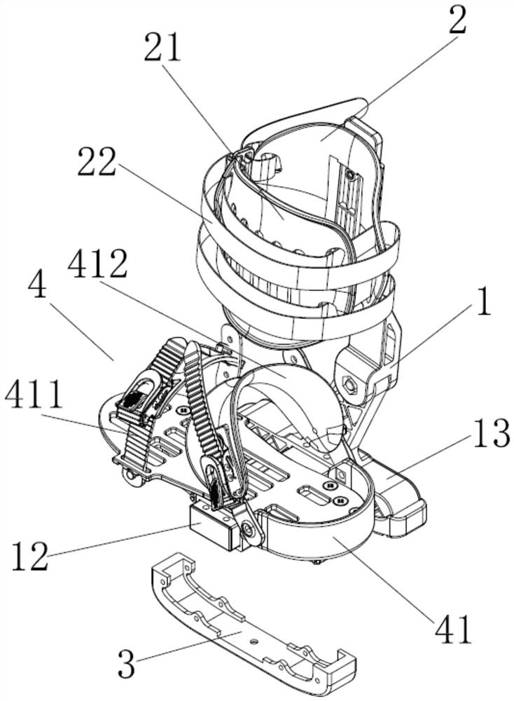
[0021] like Figure 1 to Figure 4 As shown, an O-shaped leg orthosis includes a main support rod 1, a leg binding structure 2, a ground contact fulcrum structure 3, a foot plate 4 and an overcorrection prevention device 5, and the main support rod 1 includes an inclined vertical rod part 11 , the bottom rod part 12 and the base 13, the inclined vertical rod part 11 and the bottom rod part 12 are all hinged on the base 13, the two ends of the bottom rod part 12 are provided with limit holes, the base 13 is provided with a hinge shaft 131, and the hinge shaft 131 is inserted Set in the limit hole, the end of the hinge shaft 131 is fixed by bolts, the leg binding structure 2 is installed on the upper part of the inclined pole part 11 by screws, the leg binding structure 2 includes an enclosure plate 21 and a hook and loop 22 , the two ends of the Velcro 22 are respectively hinged on the two ends of the enclosure plate 21, the foot plate 4 is arranged at the end of the bottom rod ...

Embodiment 2

[0026] like Figure 5 As shown, the anti-overcorrection device 5 is arranged on the bottom surface of the foot plate 4, and the anti-overcorrection device 5 can be lifted or fixed in height. This structure can also be replaced by other structures that achieve the same effect. The anti-overcorrection device 5 is in contact with the ground. After wearing the O-shaped leg corrector for a long time, the height of the anti-overcorrection device 5 can be adjusted according to the correction situation. The upturning range of the rear bottom rod part 12 will be reduced, thereby preventing the position of the foot plate 4 from moving too much, thereby avoiding over-correction of the O-shaped leg, and making it more comfortable and safe to use.

[0027] The O-shaped leg corrector of the present invention, the overall structure makes the center of gravity of the human body move outward, and the correction force of the calf inward is increased by its own weight through the structure. Spec...


PUM


Abstract

The invention discloses an O-shaped leg corrector. The O-shaped leg corrector comprises a main supporting rod, a leg binding structure, a grounding fulcrum structure, a foot placing plate and an excessive correction prevention device; the main supporting rod comprises an inclined vertical rod part, a bottom rod part and a base; the base is provided with a hinge shaft; the leg binding structure is installed on the upper portion of the inclined vertical rod part; the leg binding structure comprises an enclosing plate and a hook-and-loop fastener; the two ends of the hook-and-loop fastener are hinged to the two ends of the enclosing plate respectively; the grounding fulcrum structure is arranged below the foot placing plate; the foot placing plate is installed at the end, away from the inclined vertical rod part, of the bottom rod part; the foot placing plate is provided with a bandage; the bandage comprises a vamp bandage for fixing the instep and an ankle bandage for fixing the ankle; and the excessive correction preventing device is arranged below the foot placing plate, and the excessive correction preventing device can be lifted or can have a fixed height. The overall structure enables the gravity center of the human body to move outwards, the inward correction force of the shank is increased through the structure by means of the weight of the human body, and good application value is achieved.

Description

technical field [0001] The invention relates to the technical field of knee joint correction, in particular to an O-shaped leg correction device. Background technique [0002] O-shaped legs are a degenerative disease of the knee joint that mostly occurs in children, adolescents, and elderly people. The formation factors of O-shaped legs are very complicated. The more common reasons are as follows: First, genetic factors. Some patients will have O-shaped legs due to the previous generation. Deformed legs, thus acquired genetically. Secondly, the more common developmental reason is that in the process of body development, due to the lack of trace elements such as calcium and phosphorus, it leads to abnormal bone development, and finally leads to bone deformation, forming O-shaped leg deformity. In addition, the formation of O-shaped legs may also be caused by long-term bad posture or incorrect force habits. The muscle strength on both sides is unbalanced, and finally the inne...

Claims


Application Information

Patent Timeline
Patent Type & Authority Applications(China)
IPC IPC(8): A61F5/01
CPCA61F5/0123A61F2005/0137
Inventor 赵鹏
Owner 赵鹏
Learn More