This helps you quickly interpret patents by identifying the three key elements:
Problems solved by technology
Method used
Benefits of technology
Problems solved by technology
Although the patent is provided with a protective rope cover, the safety is improved, but other defects caused by the coil spring still cannot be overcome
Moreover, the arm strength device will also cause inconvenience to use by adding a grip device to the handle
Method used
Image
Click on the blue label to locate the original text in one second.
Reading with bidirectional positioning of images and text.
Examples
Embodiment 1
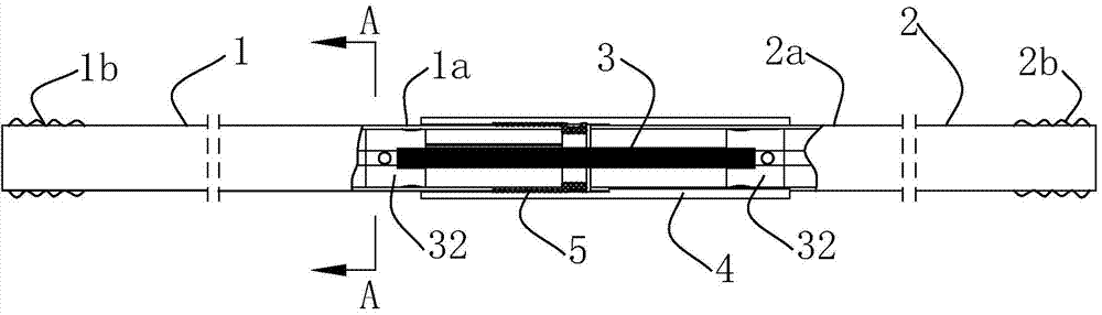
[0073] Such as figure 1 As shown, an arm strength device of the present invention includes left and right handles 1, 2, and each of the two handles 1, 2 includes a connecting end 1a, 2a and a gripping end 1b, 2b. The handle 1 in this embodiment , 2 is made of a metalpipe with an inner hole, such as a steel pipe or an aluminum alloypipe. Among them, a torsion spring 3 is connected between the connecting ends 1a, 2a of the two handles. When the holding ends 1b, 2b of the two handles are held with both hands and rotated in opposite directions, the torsion spring 3 can provide torsional resistance , which can exercise the twisting force of the arms.
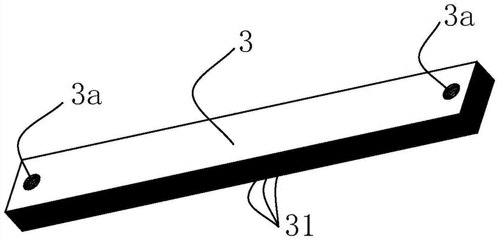
[0074] Such as figure 2 As shown, the torsion spring 3 in the present invention is composed of a plurality of spring steel sheets 31 overlapping up and down, and the two ends of these spring steel sheets 31 are provided with through holes 3a, which can be fixed by fasteners such as rivets or bolts. They are connected together. ...
Embodiment 2
[0079] Such as Figure 5 , Figure 6 As shown, in Embodiment 2 of the present invention, the two handles 1, 2 are U-shaped, the connecting ends 1a, 2a of the two handles are coaxially arranged, and the holding ends 1b, 2b of the two handles are arranged side by side, That is, viewed from the front, such as Figure 5 As shown, the holding ends 1b and 2b of the two handles overlap for a certain length, but they are separated by a certain distance in the free state. Viewed from the side, as Figure 10 As shown, an included angle is formed between the two handles 1 and 2. The structure of the torsion spring 3 in this embodiment, and the connection relationship between the torsion spring 3 and the two handles are the same as those in the first embodiment. Other structures, such as casing 4 and liner 5 can also be arranged in the same manner as in Embodiment 1.
[0080] The lengths of the two handles 1 and 2 are approximately the same. Since the holding ends 1b and 2b of the tw...
Embodiment 3
[0082] Such as Figure 7-9 As shown, the same as Embodiment 2, this embodiment also adopts two U-shaped handles and laminated torsion springs, and the two handles are also bent from round tubes, but in this embodiment, the torsion springs and the two The connection mode of the handle is different from that of Embodiment 2.
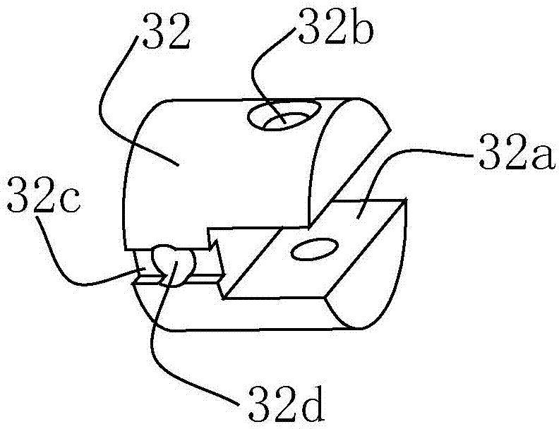
[0083] Such as Figure 7 Shown, one end of torsion spring 3 fixes a spring holder 32 in the present embodiment, and spring holder 32 is identical with above-mentioned two embodiments; Like the seat 32, a notch 33a is also provided on the spring holding seat 33, and one end of the spring steel sheet is clamped in the notch 33a, and is fixed on the spring holding seat by fasteners such as rivets or bolts. 33 on. A section of spline shaft 33b is also provided on the spring clamping seat 33, and external spline teeth are provided on the spline shaft 33b.
[0084] Such as Figure 8 As shown, the spring fixing seat 32 is fixed in the left handle 1, and the ...
PUM
Abstract
The invention discloses an arm-muscle developer. The arm-muscle developer comprises two handles, wherein each handle comprises a connecting end and a hand-holding end; a torsion spring is connected between the connecting ends of the two handles; the torsion spring consists of a plurality of overlapped spring steel sheets; the two ends of the multiple spring steel sheets are connected by tightening components; preferably, the two handles are U-shaped; the connecting ends of the two handles are coaxially arranged; the hand-holding ends of the two handles are parallel to each other, but are not on the same straight line. The arm-muscle developer uses the torsion spring consisting of the multiple spring steel sheets, has the advantages of small size, light weight, and convenience for fixing the two ends; the torsion spring is large in elastic force, unlikely to break and higher in safety; through reasonable setting of the distance between the hand-holding ends of the two U-shaped handles, the arm-muscle developer can be used as the arm-muscle developer as well as a hand-muscle developer.
Description
technical field [0001] The invention relates to a fitness equipment, in particular to an arm strength machine mainly used for exercising the muscles of arms, chest and shoulders. Background technique [0002] There are many kinds of body building equipment used for exercising muscles on the market, but basically can be divided into two classes, a class is to utilize the weight of apparatus self to provide resistance; Another kind is to utilize spring to provide resistance. The existing arm strength devices that use springs to provide resistance all use ordinary steel wire coil springs. Due to the limitation of coil spring winding ratio (wire diameter ratio), when it is necessary to provide greater resistance, the volume of the coil spring will become larger , so that the fitness equipment is larger or heavier, which not only increases the manufacturing cost, but also makes it inconvenient to store and carry. [0003] In addition, most of the functions of the existing arm st...
Claims
Application Information
Patent Timeline
Application Date:The date an application was filed.
Publication Date:The date a patent or application was officially published.
First Publication Date:The earliest publication date of a patent with the same application number.
Issue Date:Publication date of the patent grant document.
PCT Entry Date:The Entry date of PCT National Phase.
Estimated Expiry Date:The statutory expiry date of a patent right according to the Patent Law, and it is the longest term of protection that the patent right can achieve without the termination of the patent right due to other reasons(Term extension factor has been taken into account ).
Invalid Date:Actual expiry date is based on effective date or publication date of legal transaction data of invalid patent.

