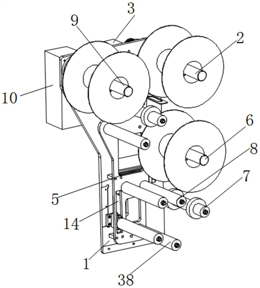
Film stripping device
A film peeling and bottom film technology, applied in thin material handling, transportation and packaging, lamination auxiliary operations, etc., can solve the problems of high labor cost, low degree of automation, high labor consumption, etc., and achieve the effect of saving labor costs.
- Summary
- Abstract
- Description
- Claims
- Application Information
AI Technical Summary
Problems solved by technology
Method used
Image
Examples
Embodiment 2
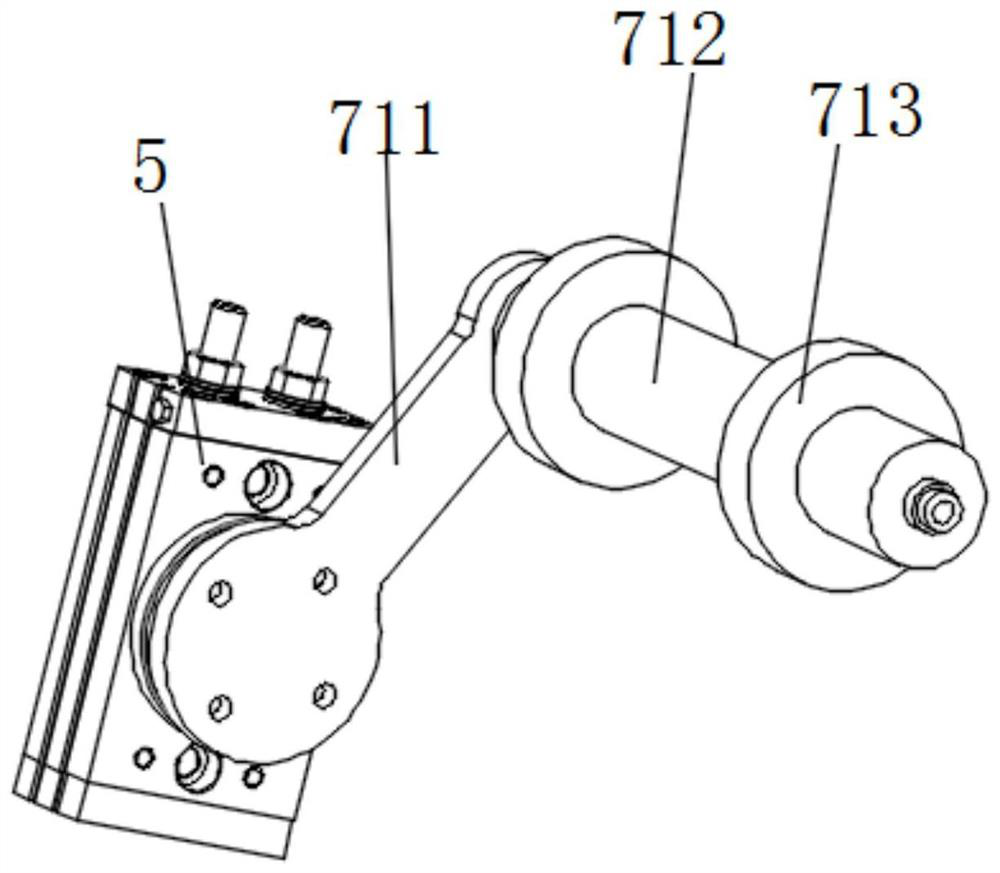
[0025] The difference from Embodiment 1 is that the connecting rod 71 includes a rotating arm 711, a driven roller 712 and a limit ring 713 connected in sequence, and the second driving member 5 is a rotating cylinder, and one end of the rotating cylinder and the rotating arm 711 can drive The rotating arm 711 rotates, and the driven roller 712 is connected to the end of the rotating arm 711 away from the rotating cylinder. Two limiting rings 713 are provided and fixed inside the ends of the driven roller 712 respectively.
Embodiment 3
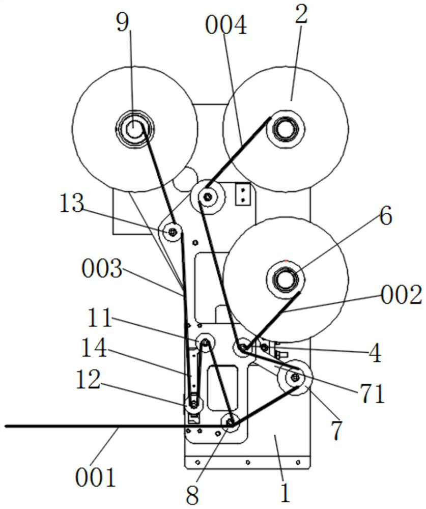
[0027] Different from Embodiment 1, the film peeling device also includes a first guide roller 11, a second guide roller 12, and a third guide roller 13. The first guide roller 11 is arranged above the second sub-spool 8, and the first guide roller 11 is arranged above the second sub-spool 8. Two guide rollers 12 are arranged under the first guide roller 11, and the third guide roller 13 is arranged under the bottom film winding shaft 9, and the longitudinal slide for installing the second guide roller 12 is provided below the frame 1. Groove 14, the second guide roller 12 can move up and down along the longitudinal chute 14, in detail, the end of the second guide roller 12 close to the frame 1 is sequentially connected with the first stop block 121, the sliding block 122 and the second stop block Block 123, the width of the first limit block 121 and the width of the second limit block 123 are greater than the width of the longitudinal chute 14, the top and bottom of the longit...
Embodiment 4
[0029] The difference from Embodiment 1 is that the first driving member 3 is a geared motor, the unwinding shaft 2, the upper film winding shaft 6 and the geared motor are connected through a belt drive, the second driving member 5 is a rotating cylinder, and the A first sensor switch and a second sensor switch are respectively installed above and below the rotary cylinder. When the first sensor switch detects that the first tension shaft 7 rotates counterclockwise to the upper limit position, the rotary cylinder stops driving the tension shaft 7 to continue to rotate counterclockwise. , stop rotating or turn to clockwise rotation, when the second sensor switch detects that the tensioning shaft 7 rotates clockwise to the lower limit position, the first rotating cylinder stops driving the first tensioning shaft 7 to continue to rotate clockwise, stop rotating or turn For counterclockwise rotation.
PUM
 Abstract
Description
Claims
Application Information
 - R&D
- Intellectual Property
- Life Sciences
- Materials
- Tech Scout
- Unparalleled Data Quality
- Higher Quality Content
- 60% Fewer Hallucinations
Browse by: Latest US Patents, China's latest patents, Technical Efficacy Thesaurus, Application Domain, Technology Topic, Popular Technical Reports.
© 2025 PatSnap. All rights reserved.Legal|Privacy policy|Modern Slavery Act Transparency Statement|Sitemap|About US| Contact US: help@patsnap.com


